Lever-type loop

A lever-type, looper technology, used in bending workpieces, metal processing equipment, metal rolling, etc., can solve the problems of material leakage, insufficient lubrication of sleeve arms, and insufficient fixation of pressure rollers, and achieves simple overall structure design. The effect of reducing maintenance costs and labor intensity

Inactive Publication Date: 2015-01-28
JIANGSU YONGGANG GROUP CO LTD
View PDF10 Cites 0 Cited by
  • Summary
  • Abstract
  • Description
  • Claims
  • Application Information

AI Technical Summary

Problems solved by technology

[0004] 1) Since the cylinder of the sleeve arm is installed in the middle of the movable swing arm, the cylinder is retracted to complete the sleeve, and the cylinder is extended to complete the sleeve. When the rolling speed of the rolling mill is fast, the movement of the cylinder will be frequent, and due to the cylinder The installation position makes the cylinder need to provide twice the force of the rolling material when the sleeve arm is unset, which will easily cause damage to the cylinder seal assembly, internal leakage, air leakage from the sliding teeth of the air pipe joint, or the pins at the head and tail of the cylinder are broken due to wear. , falling off and other reasons lead to the occurrence of material leakage
[0005] 2) Since the oil and gas pipe is directly inserted between the fixed hinge and the second movable hinge, it is located at the movable mechanism, and no fixing measures are taken, so the oil and gas pipe often falls off, which makes the sleeve arm not lubricated in place and causes wear
[0006] 3) The pressure roller in the looper is fixed by the hook head frame, and the height is adjusted by the screw, and only the coarse thread nut is positioned in the height direction of the pressure roller. Due to the characteristics of the coarse thread nut, the pressure roller is often not fixed tightly. There is a phenomenon of moving up and down during operation; in addition, because the pressure roller is in a high-temperature and high-humidity environment for a long time, the screw often rusts and dies, which leads to damage to the inner bearing and shaft of the pressure roller and cannot be replaced quickly

Method used


Image

  • Lever-type loop
  • Lever-type loop
  • Lever-type loop

Examples


Embodiment Construction

[0023] In order to deepen the understanding and recognition of the present invention, the present invention will be further described and introduced below in conjunction with the accompanying drawings.

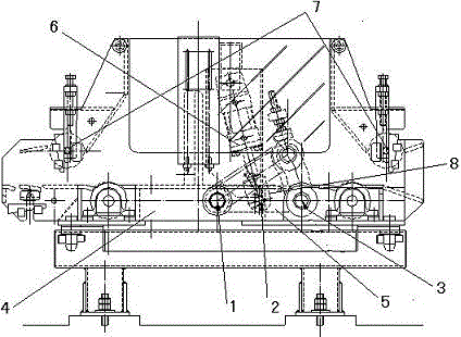
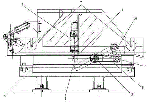
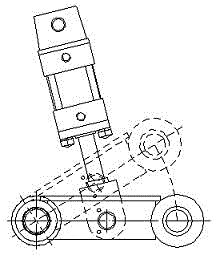
[0024] Such as figure 2 and 4 As shown, a kind of lever type looper comprises a looper frame 4, a sleeve arm 5, a sleeve cylinder 6, a pressure roller device 7, and a sleeve roller 10, and the looper frame 4 is fixedly connected with the work surface, The sleeve arm 5 is movably connected to the looper frame 4 using the first movable hinge 1 and the third movable hinge 3, and the hinge point of the sleeve cylinder 6 is installed at the rear end of the fixed hinge 2 to form a Balanced leverage effect, the jacketing cylinder 6 is fixed and hinged on the jacketing arm 5 through the cylinder ear plate 8, the jacketing shaft of the jacketing roller 10 is provided with an oil filling hole 9, and the oil and gas pipe is connected to the jacketing arm 5. The shaft of the set roller...


PUM


Abstract

The invention relates to a lever-type loop. The lever-type loop comprises a loop rack, a loop-rising cylinder, a loop-rising roller, pressing roller devices and a loop-rising arm, and is characterized in that the loop-rising cylinder is mounted at the rear end of a fixed hinging point to form a balanced lever effect; an oil filling hole is formed in a loop-rising shaft of the loop-rising roller, and an oil gas pipe on the loop-rising cylinder is fixedly connected with the loop-rising roller; the pressing roller devices are fixedly connected with the loop rack through hook head frames; a height groove is directly formed in the loop rack and replaces an original screw height adjusting device of each pressing roller device, and pressing roller shafts on the pressing roller devices are positioned by using inclined wedges. The lever-type loop provided by the invention has the characteristics of simple structural transformation, high reliability, low cost and the like.

Description

technical field [0001] The invention relates to a looper device in a steel bar workshop, in particular to a device for automatic adjustment and micro-tension rolling during the rolling process. Background technique [0002] The looper is one of the essential equipments in the modern high-speed and high-precision bar production process. It is mainly used for the automatic adjustment of the rolled material during the bar rolling process and to ensure the micro-tension rolling of the rolled material. Such as figure 1 As shown in and 3, it is a looper device used in the prior art. It mainly drives the sleeve arm through the expansion and contraction of the sleeve cylinder to perform the sleeve removal action. The sleeve cylinder is hinged at the middle position of the sleeve arm. And use pins and copper sleeves to form the first movable hinge, use long pins at the rear end hinge to fix the hinge with the rolling mill frame; The hinges are lubricated with copper bushings and o...

Claims


Application Information

Patent Timeline
IPC IPC(8): B21B41/00
Inventor 杨小洪周志军盛海军冯正平
Owner JIANGSU YONGGANG GROUP CO LTD
Why Eureka
Try Eureka