The Method of Strip Head Deviation Correction During Strip Threading in Continuous Rolling
A strip and head technology, which is applied in the field of strip head deviation correction in the process of continuous rolling and stripping, can solve the problems of poor strip head deviation correction effect and other problems.
- Summary
- Abstract
- Description
- Claims
- Application Information
AI Technical Summary
Problems solved by technology
Method used
Image
Examples
Embodiment 1
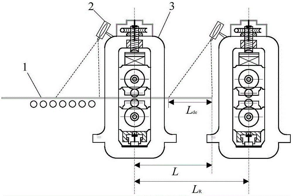
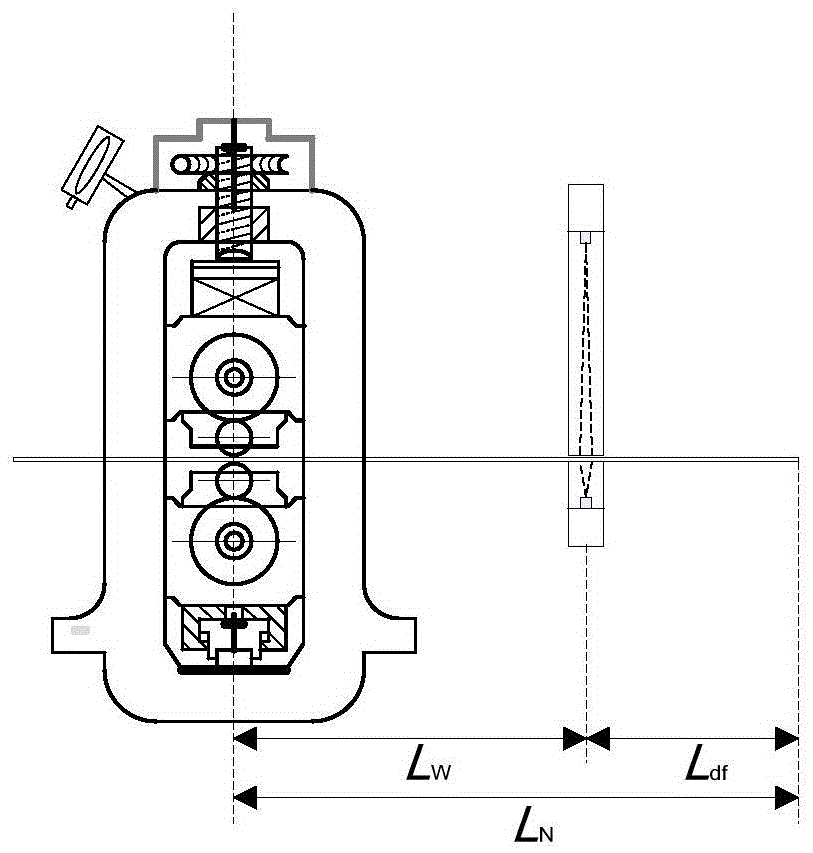
[0139] Since the distance between the roll gaps between the racks generally does not exceed 6000 mm, care should be taken to ensure the length of the sampling area L when installing the camera de Not greater than 4000 mm, preferably L de = 2500 mm, take L at the same time df = 2500 mm. The image is digitized by a high-speed image data acquisition card and sent to the computer. As the object of rolling piece size identification, the computer processes the digital image, extracts the edge information of the strip head, and obtains the final planar size of the rolled piece. When the rolled piece passes through the detection area between the racks, the signal of the head of the strip processed by the PLC system is used to control the industrial CCD camera to collect an image and send it to the computer for image acquisition and data processing. Assume that the total number of stands in the tandem mill is 4. The roller transmission motor end of the frame is equipped with a speed...
PUM
 Abstract
Description
Claims
Application Information
 - R&D
- Intellectual Property
- Life Sciences
- Materials
- Tech Scout
- Unparalleled Data Quality
- Higher Quality Content
- 60% Fewer Hallucinations
Browse by: Latest US Patents, China's latest patents, Technical Efficacy Thesaurus, Application Domain, Technology Topic, Popular Technical Reports.
© 2025 PatSnap. All rights reserved.Legal|Privacy policy|Modern Slavery Act Transparency Statement|Sitemap|About US| Contact US: help@patsnap.com


