Method for controlling single-phase non-isolated photovoltaic inverter with follow current clamping switch

A photovoltaic inverter and control method technology, applied in the control of single-phase non-isolated photovoltaic inverters and photovoltaic power generation fields, can solve the problem of affecting the current quality of the inverter, endangering personal and equipment safety, and increasing the electromagnetic interference of the system. and other problems, to achieve significant practical application and engineering application value, improve conversion efficiency, and improve the effect of common model characteristics.

Inactive Publication Date: 2015-01-21
NANJING UNIV OF POSTS & TELECOMM
View PDF4 Cites 4 Cited by
  • Summary
  • Abstract
  • Description
  • Claims
  • Application Information

AI Technical Summary

Problems solved by technology

However, the removal of the transformer leads to an electrical connection between the input and output. Due to the existence of the capacitance of the battery board to the ground, the common mode leakage ...

Method used


Image

  • Method for controlling single-phase non-isolated photovoltaic inverter with follow current clamping switch
  • Method for controlling single-phase non-isolated photovoltaic inverter with follow current clamping switch
  • Method for controlling single-phase non-isolated photovoltaic inverter with follow current clamping switch

Examples


Embodiment approach

[0047] Specifically, as an exemplary implementation, it is implemented in the following manner:

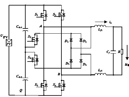
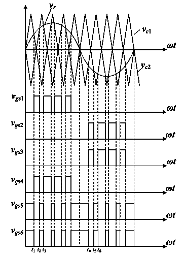
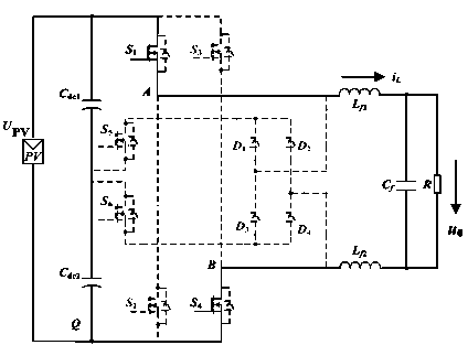
[0048] 1) Make the aforementioned first switching tube S 1 The gate-source control waveform of v gs1 and the fourth switching tube S 4 The gate-source control waveform of v gs4 same, and the aforementioned two gate-source control waveforms v gs1 , v gs4 In the positive half cycle of the inverter output current is the SPWM waveform, and the negative half cycle of the inverter output current is zero;

[0049] 2) Make the second switching tube S 2 The gate-source control waveform of v gs2 and the third switching tube S 3 The gate-source control waveform of v gs3 same, and the aforementioned two gate-source control waveforms v gs2 , v gs3 The positive half cycle of the inverter output current is zero, and the negative half cycle of the inverter output current is an SPWM waveform; and

[0050] 3) Make the fifth switching tube S 5 The gate-source control wavefor...


PUM


Abstract

The invention provides a method for controlling a single-phase non-isolated photovoltaic inverter with a follow current clamping switch. The method for controlling the single-phase non-isolated photovoltaic inverter with the follow current clamping switch comprises the steps that two-section control is conducted on switch tubes in the inverter; the gate source control waveform of the first switch tube is made to the same as that of the fourth switch tube, wherein the gate source control waveforms are SPWM waveforms in the half positive cycle during which current is output by the inverter, and the gate source control waveforms are zero waveforms in the half negative cycle during which current is output by the inverter; the gate source control waveform of the second switch tube is made the same as that of the third switch tube, wherein the gate source control waveforms are zero waveforms in the half positive cycle during which current is output by the inverter, and the gate source control waveforms are SPWM waveforms in the half negative cycle during which current is output by the inverter; the gate source control waveform of the fifth switch tube and the gate source control waveform of the sixth switch tube are made to be complementary with the gate source control waveform of the first switch tube and the gate source control waveform of the fourth switch tube in the half positive cycle during which current is output by the inverter and be complementary with the gate source control waveform of the second switch tube and the gate source control waveform of the third switch tube in the half negative cycle during which current is output by the inverter. By the adoption of the method for controlling the single-phase non-isolated photovoltaic inverter with the follow current clamping switch, the conversion efficiency of the non-isolated photovoltaic inverter can be improved, and the common-mode characteristic of the non-isolated photovoltaic inverter is improved.

Description

technical field [0001] The invention relates to the technical field of power electronic DC-AC conversion, in particular to a control method for a single-phase non-isolated photovoltaic inverter with a freewheeling clamp switch, which is suitable for photovoltaic power generation occasions. Background technique [0002] Photovoltaic grid-connected inverters require high efficiency, low cost, and can withstand the adverse effects of large output voltage fluctuations of photovoltaic cells, and their AC output must also meet high power quality. [0003] According to whether the inverter has an isolation transformer, it can be divided into isolation type and non-isolation type. The isolated photovoltaic inverter realizes the electrical isolation of the power grid and the battery panel, and ensures the safety of people and equipment, but it is bulky, expensive, and the system conversion efficiency is low. The non-isolated photovoltaic inverter structure does not contain a transfo...

Claims


Application Information

Patent Timeline
IPC IPC(8): H02M7/487H02M7/5387
CPCY02E10/56H02M7/487H02M7/53873
Inventor 马海啸叶海云袁颖
Owner NANJING UNIV OF POSTS & TELECOMM
Why Eureka
Try Eureka