
Antenna arrangement, electronic device and method for arranging the antenna arrangement

A technology of an antenna device and electronic equipment, applied in the field of communication

Active Publication Date: 2017-11-03
LENOVO (BEIJING) LTD
View PDF3 Cites 0 Cited by
  • Summary
  • Abstract
  • Description
  • Claims
  • Application Information

AI Technical Summary

Problems solved by technology

[0004] Therefore, it is difficult for existing antennas to meet the design requirements of electronic equipment while ensuring the performance of the antenna

Method used


Image

  • Antenna arrangement, electronic device and method for arranging the antenna arrangement
  • Antenna arrangement, electronic device and method for arranging the antenna arrangement
  • Antenna arrangement, electronic device and method for arranging the antenna arrangement

Examples


Embodiment Construction

[0029] The following will clearly and completely describe the technical solutions in the embodiments of the present invention with reference to the accompanying drawings in the embodiments of the present invention. Obviously, the described embodiments are some of the embodiments of the present invention, but not all of them.

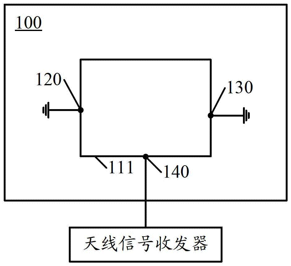
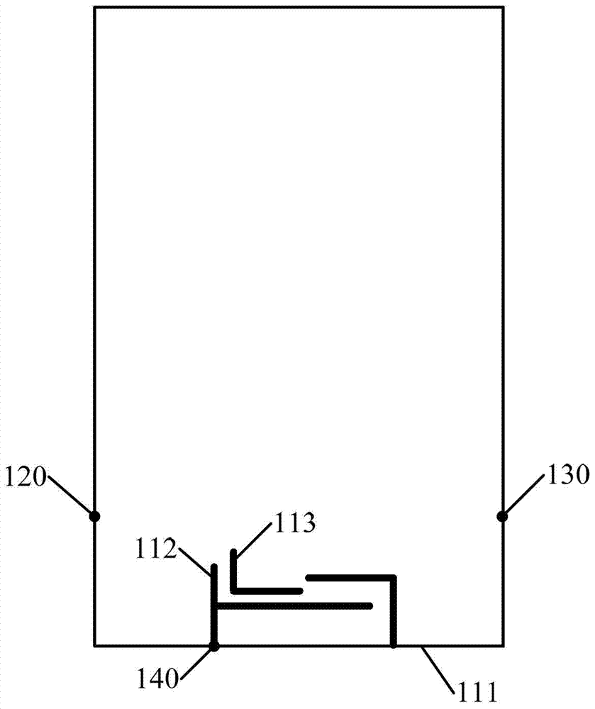
[0030] In the embodiment of the present invention, a part of the conductor on the housing of the electronic device is used to form the radiation unit of the antenna, and two ground terminals are arranged on the conductor shell area, thereby forming a complete metal Ring, without interrupting the shell, so as to meet the design requirements of the electronic equipment; and because a part of the conductor shell area is used as the radiation part, it avoids the shielding effect of the shell of the electronic equipment, thus ensuring the antenna performance of the device.

[0031] figure 1 is a block diagram schematically illustrating the antenna device 100...


PUM


Abstract

Provided are an antenna device, electronic equipment having the antenna device, and a method for setting the antenna device. The electronic device has a conductor housing and an antenna signal transceiver. The antenna device includes: a radiating unit, including a first radiating part formed by a part of the conductor shell region, and the radiating unit is used for transmitting and receiving antenna signals; a first ground terminal, located at a first position of the conductor shell region on, used to connect to the ground; the second ground terminal, located at the second position of the conductor shell area, used to connect to the ground, and the second position is different from the first position; the feed terminal is used to connect The radiation unit is coupled to the antenna signal transceiver. In the technical solutions disclosed in the embodiments of the present invention, the appearance design requirements of electronic equipment can be met while ensuring the performance of the antenna.

Description

technical field [0001] The present invention relates to the technical field of communication, and more specifically, to an antenna device, an electronic device with the antenna device and a method for setting the antenna device. Background technique [0002] With the rapid development of mobile communication technology, many electronic devices are equipped with antennas to transmit information and data, such as computers, personal digital assistants, mobile communication terminals and so on. In addition, the appearance design of the electronic device, such as metallic texture, also attracts users' attention. Therefore, it is expected that the electronic equipment has excellent antenna performance and also has a good appearance design. [0003] The antenna design of the existing electronic equipment usually adopts conventional Inverted F antenna (IFA, Planar Inverted FAntenna), monopole antenna, etc. to design the built-in antenna, and the performance of the built-in antenna...

Claims


Application Information

Patent Timeline
Patent Type & Authority Patents(China)
IPC IPC(8): H01Q1/44H01Q1/48H01Q1/22
Inventor 林辉
Owner LENOVO (BEIJING) LTD
Learn More