
Digitized high-power microwave diode reversed dynamic waveform and loss power testing system

A technology of loss power and dynamic waveform, applied in the field of digital high-power microwave diode reverse dynamic waveform and loss power test system, can solve problems such as breakdown, achieve the effect of suppressing common mode interference, enhancing reliability and accuracy

Active Publication Date: 2015-01-21
南通安广美术图案设计有限公司
View PDF9 Cites 18 Cited by
  • Summary
  • Abstract
  • Description
  • Claims
  • Application Information

AI Technical Summary

Problems solved by technology

In addition, the reverse peak voltage of the diode is closely related to the stray inductance, distributed capacitance, lead resistance, and current conversion speed, and it will encounter the phenomenon that the reverse peak voltage is much larger than the design value and will be broken down.

Method used


Image

  • Digitized high-power microwave diode reversed dynamic waveform and loss power testing system
  • Digitized high-power microwave diode reversed dynamic waveform and loss power testing system
  • Digitized high-power microwave diode reversed dynamic waveform and loss power testing system

Examples


Embodiment Construction

[0070] In order to make the purpose, technical solution and advantages of the "digitalized high-power microwave diode reverse dynamic waveform and power loss test system" of the present invention more clear, the present invention will be further described in detail below in conjunction with the accompanying drawings and embodiments. It should be understood that the specific embodiments described here are only used to explain the present invention, not to limit the present invention.

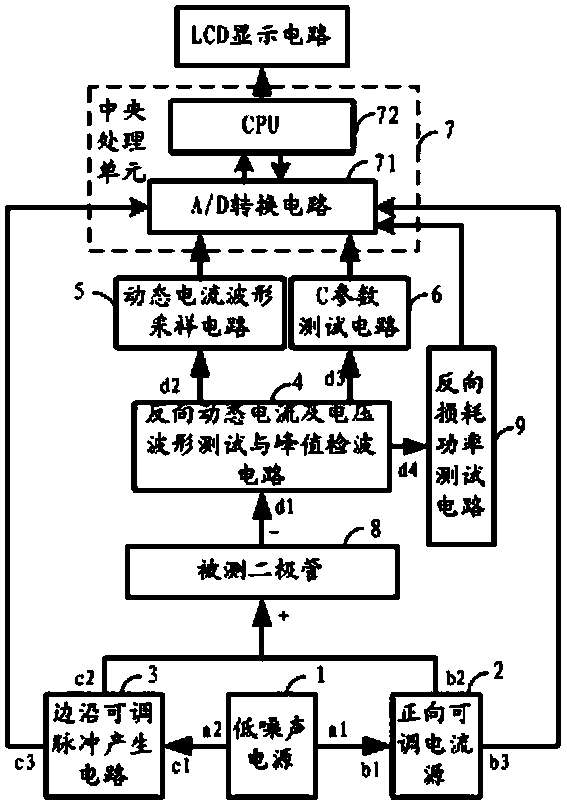
[0071] Such as figure 1 As shown, in the embodiment of the present invention, a digital high-power microwave diode reverse dynamic waveform and power loss test system is proposed, which cooperates with the tested diode 8 and includes a low-noise power supply circuit 1 and a forward adjustable current source circuit. 2. Edge adjustable pulse generation circuit 3. Reverse dynamic current and voltage waveform test and peak detection circuit 4. Dynamic current waveform sampling circuit 5. C paramete...


PUM


Abstract

The invention discloses a digitized high-power microwave diode reversed dynamic waveform and loss power testing system. The system comprises a low-noise power circuit used for providing direct voltage and applying reverse bias voltage to a diode to be tested, a forward adjustable current source circuit used for providing multiple adjustable forward currents for the diode to be tested, an edge adjustable pulse generating circuit used for providing multiple adjustable pulse modulation signals for the diode to be tested, a reverse dynamic current and voltage waveform testing and peak detection circuit used for acquiring the reverse dynamic current and voltage waveforms and peak signals of the diode to be tested, a dynamic current waveform sampling circuit used for processing the peak signals into analog signals, a C parameter testing circuit used for measuring the ratio of reverse peak voltage to bias voltage, and a central processing unit used for data processing. According to the system, by detecting performance parameters, including the reverse dynamic current, reverse dynamic voltage and loss power, of the diode, the purposes of well selecting and using the diode and improving the reliability of the diode are realized.

Description

technical field [0001] The invention relates to the fields of electronic technology and microwave diode technology, in particular to a digital high-power microwave diode reverse dynamic waveform and power loss test system. Background technique [0002] Diodes are widely used in modern high-power communication radar and other equipment, and their performance parameters (such as reverse dynamic current, reverse dynamic voltage and reverse loss power, etc.) are directly related to the stability and reliability of modern high-power communication radar and other equipment , life and efficiency. [0003] At present, the switching function of the diode in the circuit depends on the on-off characteristics of the forward and reverse currents. The instantaneous on-off of the switch is determined by the polarity of the voltage applied to both ends. There is only a small current when it is off. Since the PN junction of the diode stores many and few carriers, when the polarity of the a...

Claims


Application Information

Patent Timeline
IPC IPC(8): G01R31/26G01R21/133
Inventor 韦文生罗飞
Owner 南通安广美术图案设计有限公司
Learn More