
Method for measuring antenna impedance on ultrahigh frequency radio frequency identification electronic tag

An electronic tag and radio frequency identification technology, applied in the field of microelectronics, can solve problems such as time-consuming, high equipment requirements, and measurement accuracy, and achieve the effect of simple and fast operation and improved measurement accuracy

Active Publication Date: 2015-01-21
XIDIAN UNIV
View PDF5 Cites 6 Cited by
  • Summary
  • Abstract
  • Description
  • Claims
  • Application Information

AI Technical Summary

Problems solved by technology

The measurement accuracy of this method depends on the modeling of the fixture; secondly, this method also needs to convert various parameters, such as S parameters, ABCD parameters, and Y parameters, which is time-consuming
[0010] Since the measurement accuracy of the above four measurement methods depends on the accuracy of the measurement equipment or the modeling of the measurement equipment, the requirements for the equipment are high, the measurement results are easily affected by the equipment and there are deviations, and the fourth method has a variety of calculations and conversions. It is time-consuming to set parameters, so they cannot be well applied to the measurement of antenna impedance on UHF RFID electronic tags

Method used


Image

  • Method for measuring antenna impedance on ultrahigh frequency radio frequency identification electronic tag
  • Method for measuring antenna impedance on ultrahigh frequency radio frequency identification electronic tag
  • Method for measuring antenna impedance on ultrahigh frequency radio frequency identification electronic tag

Examples


Embodiment Construction

[0032] The present invention will be described in detail below in conjunction with the accompanying drawings and embodiments. It should be understood that the specific embodiments described here are only used to explain the present invention, not to limit the present invention.

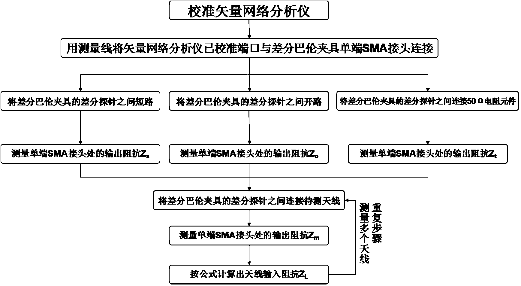
[0033] refer to figure 1 , the measurement steps of the present invention are as follows:

[0034] Step 1, set up the measurement system.

[0035] 1.1) Select one vector network analyzer, one differential balun fixture, one measurement line and one electronic calibration unit:

[0036] The vector network analyzer is selected but not limited to the AGILENTE5071C model;

[0037] The electronic calibration part is selected but not limited to 02916 type;

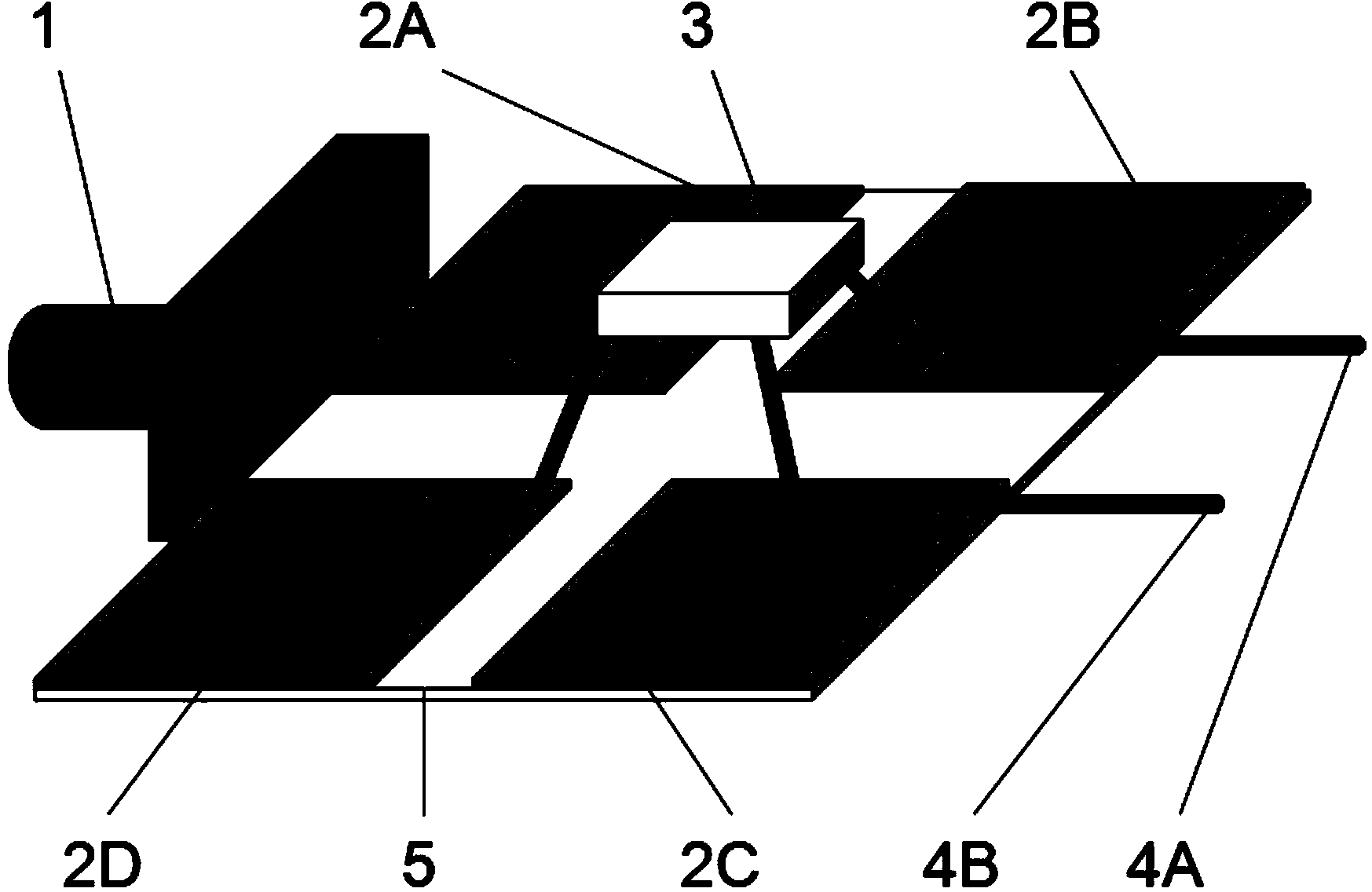
[0038] The differential balun fixture is used to change the single-ended signal at the single-ended SMA connector 1 into a differential double-ended signal at the differential double-ended probe 4. The differential double-ended signals have the same...


PUM


Abstract

The invention discloses a method for measuring antenna impedance on an ultrahigh frequency radio frequency identification electronic tag. The method mainly solves the problem of influence on measurement precision caused by precision of an impedance measurement device. The method comprises the implement steps of first, calibrating a vector network analyzer for measurement through an electronic calibration part; second, connecting the port of the vector network analyzer with a single-end SMA connector of a difference balun clamp through a measurement line; third, sequentially measuring input impedance values of the difference end of the difference balun clamp under the states of short circuit, open circuit and connection with 50-ohm resistance; fourth, measuring the input impedance value of the single-end SMA connector under the state that the difference end of the difference balun clamp is connected with a balancing antenna to be measured; fifth, performing calculation according to the above four measured parameters to obtain the input impedance of the radio frequency identification balancing antenna. By means of the method, the influence on the measurement result caused by precision of the measurement device is avoided. The method has the advantages of being simple and quick in operation and high in measurement precision and can be suitable for measuring the input impedance of the balancing antenna on the ultrahigh frequency radio frequency identification electronic tag in a large-batch mode.

Description

technical field [0001] The invention belongs to the field of microelectronics and relates to ultra-high frequency radio frequency identification technology, in particular to a method for measuring antenna impedance, which can be used for mass measurement of balanced antenna input impedance on ultra-high frequency radio frequency identification electronic tags. Background technique [0002] UHF RFID is a technology that includes storing unique identification information in a chip, and using radio frequency to identify, track or manage objects attached to the chip. Ultra-high frequency radio frequency identification UHF RFID has the characteristics of high accuracy, large storage capacity, resistance to harsh environments, and high security. It has been widely used in production, logistics, transportation, anti-counterfeiting and other fields. With the continuous improvement and maturity of related technologies , Ultra-high frequency radio frequency identification UHF RFID tec...

Claims


Application Information

Patent Timeline
Patent Type & Authority Applications(China)
IPC IPC(8): G01R27/02
Inventor 李小明庄奕琪闫昕王博刘伟峰李振荣
Owner XIDIAN UNIV
Learn More