Pump station base, pump station and mounting method for pump station
A technology for pumping stations and energy dissipation devices, applied in water supply devices, waterway systems, drainage structures, etc., can solve the problems of no public installation of pumping stations, complex and undisclosed elimination of water pump units, etc. The effect of convenient transportation
- Summary
- Abstract
- Description
- Claims
- Application Information
AI Technical Summary
Problems solved by technology
Method used
Image
Examples
Embodiment approach 1
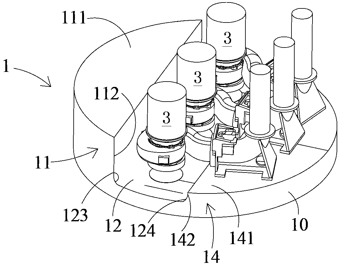
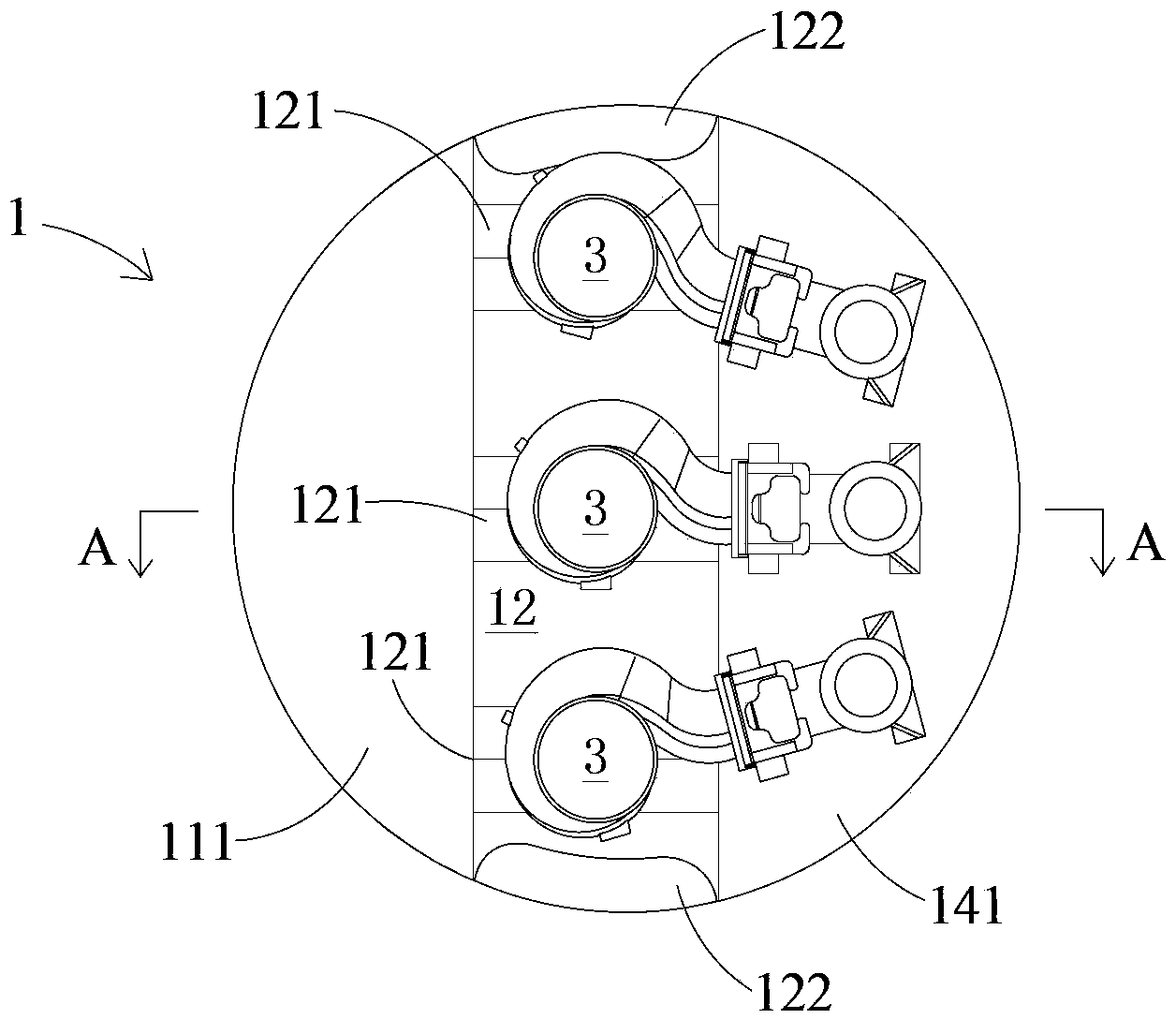
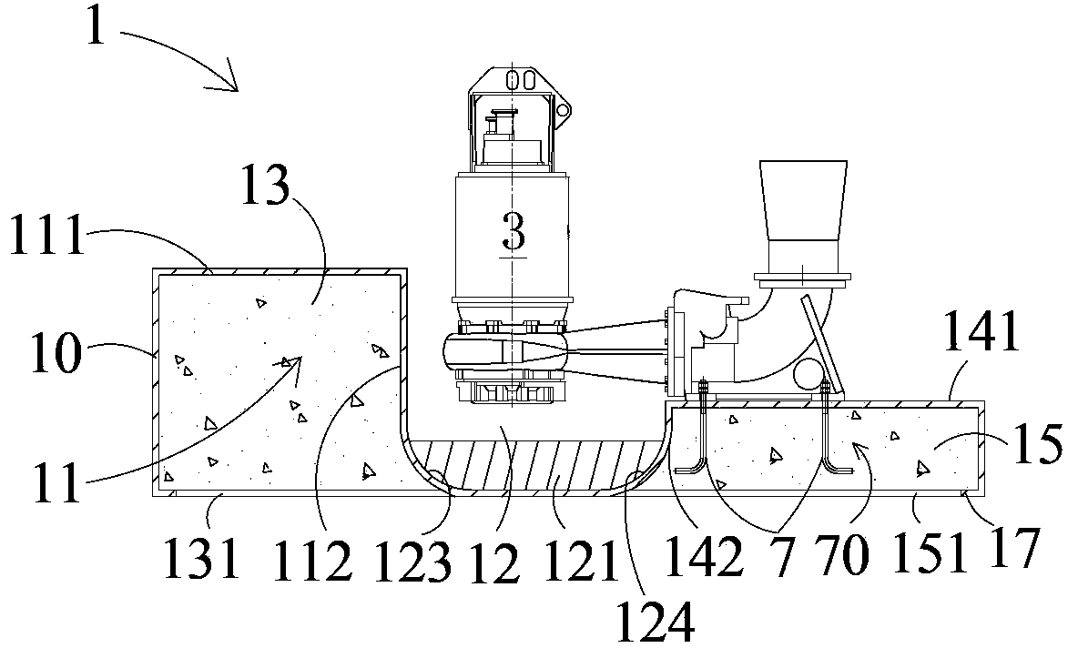
[0096] Such as Figure 1A , Figure 1B , Figure 1C and Figure 1D As shown, the first embodiment of the prefabricated pumping station foundation 1 of the present invention can be made of sheet material, such as glass steel plate or metal plate. The first embodiment of the prefabricated pump station foundation 1 includes a foundation side wall 10 , a deflector, a first step 11 , a second step 14 and a suction pit 12 .
[0097] The base side wall 10 is cylindrical, such as a cylinder. The bottom ends of the base side walls 10 are on the same plane. The lower end of the base side wall 10 has a bottom edge 17 bent inwardly of the base side wall 10 . The lower end of the base side wall 10 may also be provided with an outwardly bent bottom edge (not shown in the figure), or an inwardly bent bottom edge 17 and an outwardly bent bottom edge may be provided at the same time.
[0098] The first step 11 includes a top wall 111 and a side wall 112 . The function of the deflector is...
Embodiment approach 2
[0109] Such as figure 2 As shown, the structure of the second embodiment of the prefabricated pumping station base of the present invention is basically the same as that of the first embodiment, the only difference is that the side wall 10 of the base extends upwards to form an extension wall, and the top end of the extension wall is located on the same horizontal plane. At this time, if the height of the extension wall is high enough, it can be used as the cylinder wall of the prefabricated pumping station. In addition, a socket 16 can also be welded or integrally formed on the top end of the extension wall, and the socket 16 can be used to connect with the cylinder wall of the prefabricated pumping station.
[0110] Other structures of the second embodiment of the prefabricated pumping station base are the same as those of the first embodiment, and will not be repeated here.
Embodiment approach 3
[0112] Such as Figure 3A and Figure 3B As shown, the third embodiment of the prefabricated pumping station foundation of the present invention further includes a base plate 9 and at least one fixing structure 90 on the basis of the second embodiment. The base plate 9 can be made of reinforced concrete, but not limited thereto, and it can also be made of other materials such as metal or fiberglass. The base plate 9 can be circular or rectangular or other shapes, and the area of the side of the base plate 9 in contact with the ground is larger than the area of the side of the base of the prefabricated pump station in contact with the ground.
[0113] The fixing structure 90 includes a plurality of steel bars 91 arranged upward, that is, the lower ends of the steel bars 91 are fixed to the base plate 9 . Further, the fixing structure 90 also includes a plurality of transverse steel bars 92 welded and fixed to the steel bar 91 to further enhance the firmness of the connect...
PUM
 Abstract
Description
Claims
Application Information
 - R&D
- Intellectual Property
- Life Sciences
- Materials
- Tech Scout
- Unparalleled Data Quality
- Higher Quality Content
- 60% Fewer Hallucinations
Browse by: Latest US Patents, China's latest patents, Technical Efficacy Thesaurus, Application Domain, Technology Topic, Popular Technical Reports.
© 2025 PatSnap. All rights reserved.Legal|Privacy policy|Modern Slavery Act Transparency Statement|Sitemap|About US| Contact US: help@patsnap.com


