
PCB tinning method and device

A pad and connection technology, applied in the field of tinning on PCB, can solve the problems of poor tinning, unqualified, and lowering, and achieve the effect of improving tinning rate, increasing tinning rate, and ensuring soldering quality

Active Publication Date: 2015-01-07
INSPUR BEIJING ELECTRONICS INFORMATION IND
View PDF4 Cites 4 Cited by
  • Summary
  • Abstract
  • Description
  • Claims
  • Application Information

AI Technical Summary

Problems solved by technology

However, for the connection between the ground / power supply pin and the solder hole designed by the three-layer flower pad technology, when the thickness of the PCB exceeds 2 mm, and the PCB layer that the ground / power supply pin needs to be connected to is the bottom of the PCB and the first tin When the number of layers of the ground / power pin is increased, the heat dissipation rate of the solder does not decrease, so that the tin speed does not increase, so the tin rate of the ground / power pin decreases, sometimes even Reduced to the unqualified level, resulting in poor tinning, thereby reducing the soldering quality of the PCB

Method used

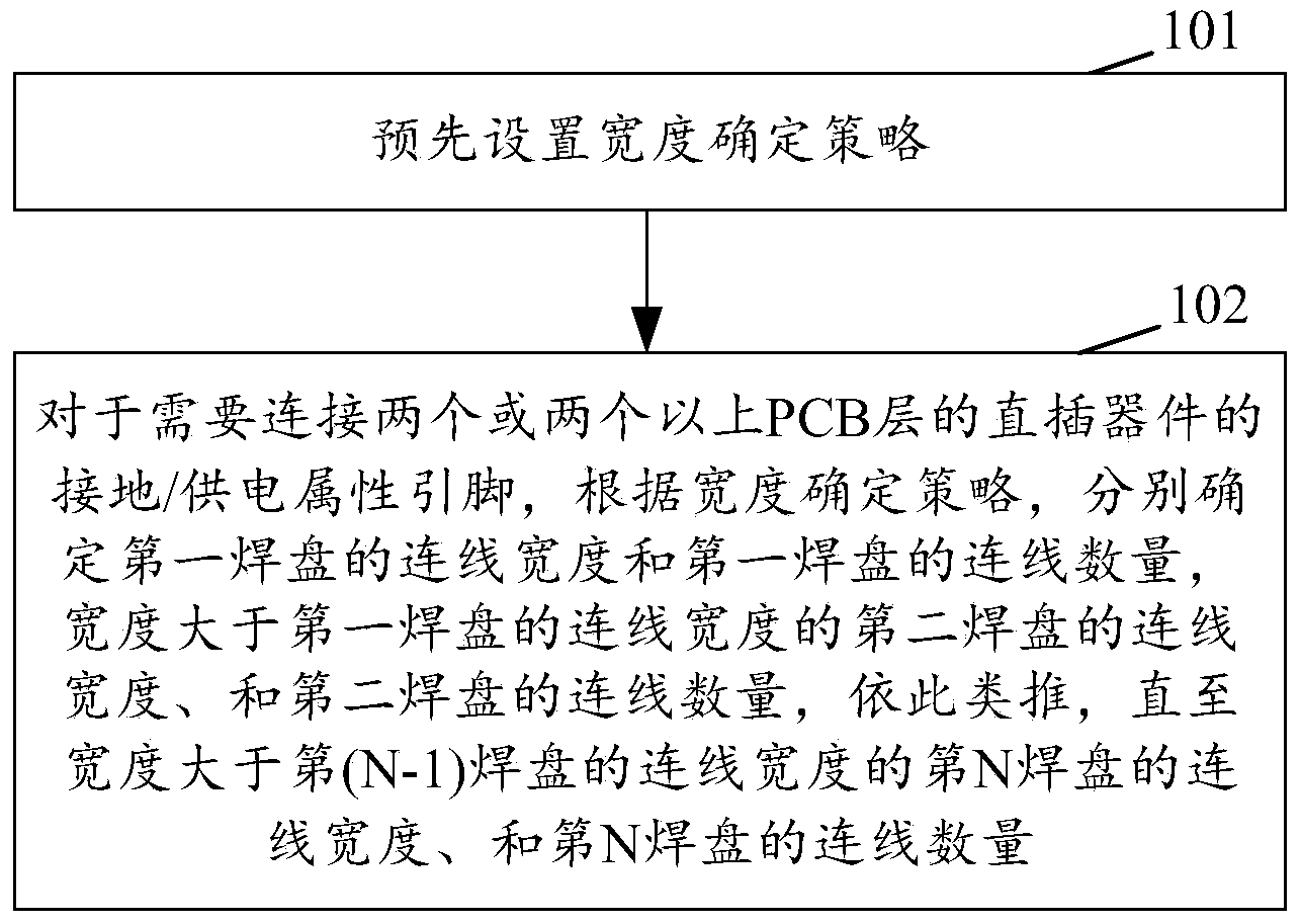
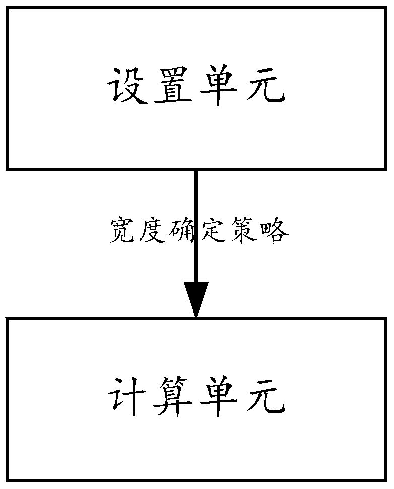

Image

  • PCB tinning method and device
  • PCB tinning method and device
  • PCB tinning method and device

Examples


Embodiment Construction

[0038] In order to make the object, technical solution and advantages of the present invention clearer, the process of the embodiments of the present invention will be described in detail below in conjunction with the accompanying drawings. It should be noted that, in the case of no conflict, the embodiments in the present application and the features in the embodiments can be combined arbitrarily with each other.

[0039] The steps shown in the flowcharts of the figures may be performed in a computer system, such as a set of computer-executable instructions. Also, although a logical order is shown in the flowcharts, in some cases the steps shown or described may be performed in an order different from that shown or described herein.

[0040] It should be noted first that the ground / power supply pins in this article refer to the ground / power supply pins of in-line devices that need to connect two or more PCB layers.

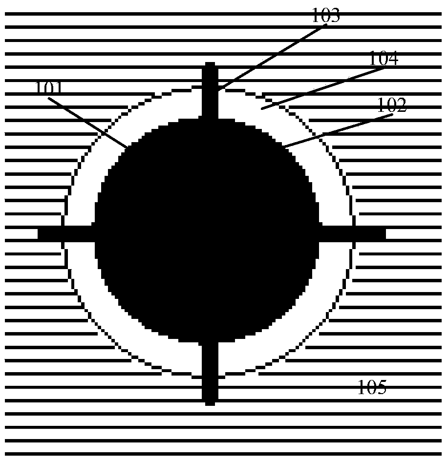
[0041] figure 1 A schematic diagram of a pad on one layer...


PUM


Abstract

The invention discloses a PCB tinning method and device. The method comprises the steps that a width determination strategy is preset; for a grounding / power supply attribute pin needing to be connected with two or more direct-insertion devices of a PCB layer, according to the width determination strategy, the width and number of connecting lines of first soldering pads are determined, the width and number of connecting lines of second soldering pads with the width of the connecting lines larger than the width of the connecting lines of the first soldering pads are determined, and the process is conducted in this way till the width and number of connecting lines of Nth soldering pads with the width of the connecting lines larger than the width of connecting lines of (N-1)th soldering pads are determined. According to the technical scheme, when spray soldering is carried out on a PCB, the heat dissipation speed of tin soldering is reduced, so that the tinning speed of soldering holes is increased, and the tinning rate of the soldering holes is increased.

Description

technical field [0001] The invention relates to a printed circuit board (PCB) design technology, in particular to a method and a device for realizing tinning on a PCB during upspray welding. Background technique [0002] The upper spray tin welding technology is a welding technology often used in PCB welding. When using the upward spray welding technology for welding, the PCB is set on the welding torch, and the welding torch is welded by spraying tin upward. After the PCB is welded by spray welding technology, the welding quality is usually judged by various parameters, and the tin coating rate is an important parameter for judging the welding quality. The tin rate indicates the degree of tin injection into the PCB solder hole, where the solder hole is the via hole of the PCB where the pins of the in-line device are inserted. [0003] The connection between the in-line pins and the PCB layer is realized by soldering the pins to the pads on the PCB layer. In-line device p...

Claims


Application Information

Patent Timeline
Patent Type & Authority Applications(China)
IPC IPC(8): H05K3/40H05K3/34
CPCH05K3/34H05K3/40
Inventor 宋明哲宗艳艳范晓丽
Owner INSPUR BEIJING ELECTRONICS INFORMATION IND
Learn More