
Wire clearance bevel gear type adjusting mechanism of automatic wire cutting and peeling machine

A technology of adjusting mechanism and driving bevel gear, applied in belt/chain/gear, mechanical equipment, transmission device, etc., can solve the problems of reduced efficiency, poor wire processing, difficult installation and adjustment, etc.

Inactive Publication Date: 2015-01-07
LUOYANG XINSILU ELECTRIC
View PDF8 Cites 0 Cited by
  • Summary
  • Abstract
  • Description
  • Claims
  • Application Information

AI Technical Summary

Problems solved by technology

However, the specifications of the wires are not the same. Some wires are particularly hard, and some wires are not easy to process. Therefore, when the equipment is working, it is necessary to make some adjustments to the gap between the upper and lower wire drive wheels after the wires are pressed, so as to better However, the method of adjusting the gap only by adjusting the air pressure is cumbersome and time-consuming. Therefore, the automatic wire cutting and stripping machine needs a gap adjustment mechanism for the wire drive wheel
[0003] The existing automatic wire cutting and stripping machine wire drive wheel gap adjustment mechanism is a rack drive type, which is not only difficult to install and adjust, but also has low transmission accuracy
When adjusting the gap of the wire transmission wheel of the equipment, the rack drive can adjust the gap of at least one tooth at a time, and it is impossible to make precise fine-tuning. Therefore, the pressure may be too small to completely compress the wire, or the pressure may be too large. The situation of being compressed and deformed will lead to rework and waste of the processed wire harness, which reduces efficiency and causes waste

Method used


Image

  • Wire clearance bevel gear type adjusting mechanism of automatic wire cutting and peeling machine
  • Wire clearance bevel gear type adjusting mechanism of automatic wire cutting and peeling machine

Examples


Embodiment Construction

[0025] In order to further explain the technical means and effects adopted by the present invention to achieve the intended purpose of the invention, the specific implementation of the bevel gear type adjustment mechanism for the wire gap of the automatic wire cutting and stripping machine proposed according to the present invention will be given below in conjunction with the accompanying drawings and preferred embodiments. Mode, method, feature and effect thereof are as follows in detail.

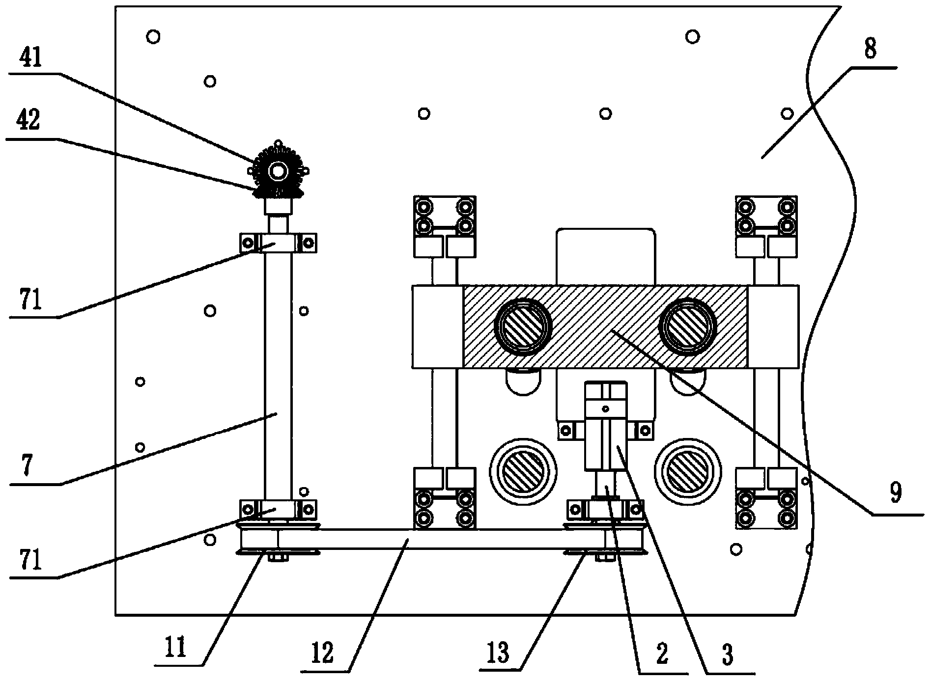
[0026] The structural features of the bevel gear type adjustment mechanism for the wire gap of the automatic wire cutting and stripping machine of the present invention are: the hand wheel 6 is connected to the active bevel gear 41 through the horizontal shaft 5, the passive bevel gear 42 is installed on the vertical shaft 7, the horizontal shaft 5 and the fixed vertical shaft 7 The vertical shaft supports 71 are all installed on the frame 8, so that the driving bevel gear 41 and the driven...


PUM


Abstract

The invention relates to a wire clearance bevel gear type adjusting mechanism of an automatic wire cutting and peeling machine. The wire clearance bevel gear type adjusting mechanism of the automatic wire cutting and peeling machine comprises an active synchronizing wheel (11), a synchronous belt (12), a passive synchronizing wheel (13), a lead screw (2), a lifting nut (3), an active bevel gear (41), a passive bevel gear (42) and a wire pressing mechanism (9), wherein the active bevel gear (41) and the passive bevel gear (42) are perpendicularly meshed, the passive bevel gear (42) is connected with the active synchronizing wheel (11) through a vertical shaft (7), the active synchronizing wheel (11) is connected with the passive synchronizing wheel (13) through the synchronous belt (12), the passive synchronizing wheel (13) is connected with the lead screw (2), the lead screw (2) is connected with the lifting nut (3), and the lifting nut (3) moves up and down to drive the wire pressing mechanism (9) to work. By means of the wire clearance bevel gear type adjusting mechanism, fine adjustment can be carried out on wire clearances of the automatic wire cutting and peeling machine and the purpose of machining high-quality wiring harnesses efficiently is achieved.

Description

technical field [0001] The invention relates to an automatic wire cutting and stripping machine, in particular to an automatic wire cutting and stripping machine with a bevel gear adjustment mechanism for the wire gap. Background technique [0002] When the automatic wire cutting and stripping machine starts to work, the upper wire driving wheel and the lower wire driving wheel compress the wire passing through the middle of the two wheels under the action of air pressure, so as to realize the purpose of transmitting the wire. However, the specifications of the wires are not the same. Some wires are particularly hard, and some wires are not easy to process. Therefore, when the equipment is working, it is necessary to make some adjustments to the gap between the upper and lower wire drive wheels after the wires are pressed, so as to better However, the method of adjusting the gap only by adjusting the air pressure is cumbersome and time-consuming. Therefore, the automatic wir...

Claims


Application Information

Patent Timeline
IPC IPC(8): H02G1/00H02G1/12F16H37/12
Inventor 王进彬杜延安林杰刘杰
Owner LUOYANG XINSILU ELECTRIC
Learn More