
Low-noise integrated centrifugal fan

A centrifugal fan, low-noise technology, applied in liquid fuel engines, mechanical equipment, machines/engines, etc., can solve the problems of high vibration noise, unstable shafting, and excessive vibration of centrifugal fans, and achieve high power density, structural Compact, low-frequency vibration reduction effect

Inactive Publication Date: 2015-01-07
中国船舶重工集团公司第七0四研究所
View PDF14 Cites 5 Cited by
  • Summary
  • Abstract
  • Description
  • Claims
  • Application Information

AI Technical Summary

Problems solved by technology

[0005] (2) The traditional centrifugal fan has large vibration and noise, large volume and heavy weight, and is a low power density device;
[0006] (3) The impeller of the traditional centrifugal fan is supported by a cantilever. During the operation of the impeller, the shaft system is not stable enough to easily generate excessive vibration

Method used


Image

  • Low-noise integrated centrifugal fan
  • Low-noise integrated centrifugal fan
  • Low-noise integrated centrifugal fan

Examples


Embodiment 1

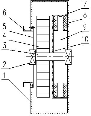
[0026] Example 1: as figure 1 As shown, a low-noise integrated centrifugal fan includes a volute 1, a support bearing 2, a main shaft 3, an impeller 4, an inlet deflector 5, an inlet flange 6, a motor housing 7, a flattened motor stator 8, The flattened motor rotor 9 and the flattened motor support bearing 10 .

[0027] The impeller 4 is installed on the main shaft 3, the flattened motor rotor 9 is installed on the main shaft 3, the flattened motor stator 8 is installed on the volute 1 and the flattened motor housing 7, respectively, the inlet deflector 5 and the inlet flange 6 Installed on the volute 1, the main shaft 3 is respectively installed on the volute 1 and the inlet deflector 5 through the support bearing 2, and the impeller 4 is rotated to do work by the rotation of the flattened motor rotor 8, and then the mechanical energy is converted into the pressure energy of the gas to be transported. and kinetic energy.

Embodiment 2

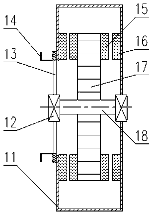
[0028] Embodiment 2: as figure 2 As shown, a low-noise integrated centrifugal fan includes a volute 11 , a support bearing 12 , an inlet deflector 13 , an inlet flange 14 , a flattened motor rotor 15 , a flattened motor stator 16 , an impeller 17 , and a main shaft 18 .

[0029] The impeller 17 is installed on the main shaft 18, the flat motor rotor 15 is installed on the impeller 15, the flat motor stator 16 is installed on the volute 11, the inlet deflector 13 and the inlet flange 14 are installed on the volute 11, and the main shaft 17 The support bearing 12 is respectively installed on the volute 11 and the inlet deflector 13, and the rotor 15 of the flattened motor is rotated to drive the impeller 17 to rotate to do work, and then convert the mechanical energy into the pressure energy and kinetic energy of the conveyed gas.

[0030] In the above embodiment, in addition to the design of installing the flattened motor part inside the fan volute, the flattened motor part ca...


PUM


Abstract

The invention relates to a low-noise integrated centrifugal fan. The low-noise integrated centrifugal fan comprises a volute and a main shaft which are used for installing a fan impeller and a motor; one lateral side of an opening of the volute is fixedly connected with an inlet diversion device; the motor is a flattened motor which is formed by a flattened motor rotor and a flattened motor stator; two ends of the main shaft are arranged on the volute and the inlet diversion device through supporting bearings respectively; the main shaft is provided with the impeller which is driven by the flattened motor rotor to rotate and apply work so as to enable the mechanical energy to be converted into the pressure energy and the kinetic energy of the conveyed gas. According to the low-noise integrated centrifugal fan, all the functions of the traditional centrifugal fan can be implemented, meanwhile the size can be small, the weight can be light, the installation is convenient, the detachment and the installation are easy, a series of fans can be designed, and the industrialization of the integrated centrifugal fan can be possible.

Description

technical field [0001] The invention relates to a centrifugal fan, in particular to a low-noise centrifugal fan for ships. Background technique [0002] In the traditional fan design, the aerodynamic design is carried out according to the performance parameters of the fan, and then the fan design, the selection of the fan drive motor, the selection of the vibration isolation device, etc., the design of each component of the fan system is divided, and the fan manufacturer only produces the fan, The supporting motor is outsourced, the motor manufacturer does not know much about the working conditions of the motor, there is insufficient communication, and there is a lack of consideration for the overall matching of the fan. The design process in this way is relatively simple. Due to the division of the design process, there is a power matching problem between the fan and the motor. Therefore, in terms of vibration, it is easy to cause the vibration of the shaft system and the u...

Claims


Application Information

Patent Timeline
IPC IPC(8): F04D25/08F04D29/66
CPCF04D25/08F04D29/663
Inventor 李国平周璞柳瑞锋符栋梁陈长盛马振来
Owner 中国船舶重工集团公司第七0四研究所
Learn More