Construction method for forming grooves and holes and replacing large-diameter piles with small-diameter piles

A technology for groove-forming construction and construction methods, applied in excavation, sheet pile walls, foundation structure engineering, etc., can solve problems such as high efficiency and low construction difficulty, reduce noise emissions, avoid economic losses, and efficiently form grooves and holes Effect

Active Publication Date: 2015-01-07
GUANGDONG FOUND ENG GRP CO LTD
View PDF3 Cites 13 Cited by
  • Summary
  • Abstract
  • Description
  • Claims
  • Application Information

AI Technical Summary

Problems solved by technology

[0003] In order to solve the above problems, the present invention provides a method for forming grooves and holes under hard rock geological conditions. The method has low construction difficulty and high efficiency, and avoids the occurrence of partial holes, hammer jamming, and difficult rock entry under complex geological conditions. etc. effectively solve the problems of underground diaphragm wall trough formation and large-diameter cast-in-situ pile formation under high rock surface and hard rock geological conditions; in addition, the present invention also provides a construction method in which large-diameter piles are replaced by multiple small-diameter piles , which solves the construction problem of large-diameter piles entering the rock under the condition of high rock face, can speed up the construction progress and avoid the loss of construction period

Method used


Image

  • Construction method for forming grooves and holes and replacing large-diameter piles with small-diameter piles
  • Construction method for forming grooves and holes and replacing large-diameter piles with small-diameter piles
  • Construction method for forming grooves and holes and replacing large-diameter piles with small-diameter piles

Examples


Embodiment Construction

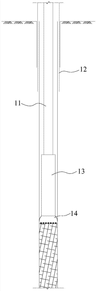
[0039] refer to Figure 1 to Figure 7 , The down-the-hole hammer is a pneumatic impact tool driven by compressed air. The part of the down-the-hole hammer that enters the formation includes a drill pipe 11 , a casing 12 , a hammer body 13 and a hammer head 14 . The air with a certain pressure provided by the air compressor drives the piston in the cylinder of the down-the-hole hammer to move repeatedly in the axial direction, so that the hammer head 14 at the end of the down-the-hole hammer rotates and produces impact effect. The impact energy and impact frequency can be directly transmitted to the hammer head 14, and then driven by the rotation of the drill pipe 11 to form a pulsating crushing ability for the rock, thereby crushing and destroying the rock and soil to achieve the effect of entering the rock and forming a hole. At the same time, the compressed air discharged by the down-the-hole hammer is used to discharge the broken rock particles out of the body, thereby real...


PUM


Abstract

The invention discloses a construction method for forming grooves and holes and replacing large-diameter piles with small-diameter piles. The method mainly includes the steps of forming the grooves in an underground continuous wall with the aid of a DTH hammer, forming the holes in the large-diameter piles with the aid of the DTH hammer and replacing the large-diameter piles with the small-diameter piles equivalently through the DTH hammer. Compared with a conventional groove and hole forming method, the construction method has the advantages that the defects that rock entering efficiency is low, holes are deviated, the hammer is stuck and even holes are difficult to form in the construction process under the comprehensive complicated geological conditions such as high-rock surface layers, hard stratums and slope stratums can be effectively overcome, the rock entering construction efficiency during grooving of the underground continuous wall and hole forming of the large-diameter piles can be greatly improved, the technical problems of the rock entering groove and hole forming construction under the complicated geological conditions such as high rock surface layers and hard stratums are solved, the construction quality is stable and reliable, the requirements for safety civilization and environmental construction are met, and economic loss and construction time loss of a project can be effectively avoided.

Description

technical field [0001] The invention is used in the field of foundation construction, and in particular relates to a construction method in which grooves are formed, holes are formed, and large-diameter piles are replaced by multiple small-diameter piles. Background technique [0002] In the trenching construction of the underground diaphragm wall, the traditional method is to use a circular hammer to break the rock mass to form a hole, and then use a square hammer to repair the hole and form a trench; in the process of forming a large-diameter pile under hard rock geological conditions, conventional The best method is to use a pile driver with low efficiency to form a hole. These methods all have obvious disadvantages such as low efficiency, long construction period and high cost. Grooving and hole formation in rocks has always been a difficult point in underground engineering construction, especially when entering rocks after passing through weak strata, and when encounte...

Claims


Application Information

Patent Timeline
Patent Type & Authority Applications(China)
IPC IPC(8): E02D17/06E02D5/34
CPCE02D5/34E02D17/06
Inventor 钟国辉傅伟强龚胜黄喜雄廖志辉易尚林
Owner GUANGDONG FOUND ENG GRP CO LTD
Why Eureka
Try Eureka