Self-elevating drilling platform cantilever beam sliding device

A technology for drilling platforms and sliding devices, applied in water conservancy projects, artificial islands, underwater structures, etc., can solve the problems of increased processing costs, difficult control, limited bearing capacity, etc., to reduce geometric deformation or bending, The effect of high safety and reliability and large carrying capacity

Active Publication Date: 2015-01-07
SICHUAN HONGHUA PETROLEUM EQUIP
View PDF6 Cites 3 Cited by
  • Summary
  • Abstract
  • Description
  • Claims
  • Application Information

AI Technical Summary

Problems solved by technology

It is difficult to process holes on the surface of the pin guide rail, especially when the track is long, which increases the processing cost
[0005] 2. When the pin moves, the top of the pin is in direct contact with the surface of the guide rail. When the friction force is large, it is easy to cause scratches on the surface of the guide rail. At the same time, when the pin is working, the stress concentration at the corresponding pin hole on the pin and the guide rail is relatively large, which often causes the guide rail to be damaged. Partial damage at the pin hole, poor reliability and limited bearing capacity
[0006] 3. When the cantilever beam slides in the opposite direction, it is necessary to manually change the direction of the pin, and at the same time, the pin-type sliding device moves in a walking manner, which has relatively low work efficiency and is difficult to locate accurately
[0007] 4. The number of sliding hydraulic pressure is large and the synchronization of sliding hydraulic pressure is high, so the control is difficult

Method used


Image

  • Self-elevating drilling platform cantilever beam sliding device
  • Self-elevating drilling platform cantilever beam sliding device
  • Self-elevating drilling platform cantilever beam sliding device

Examples


Embodiment 1

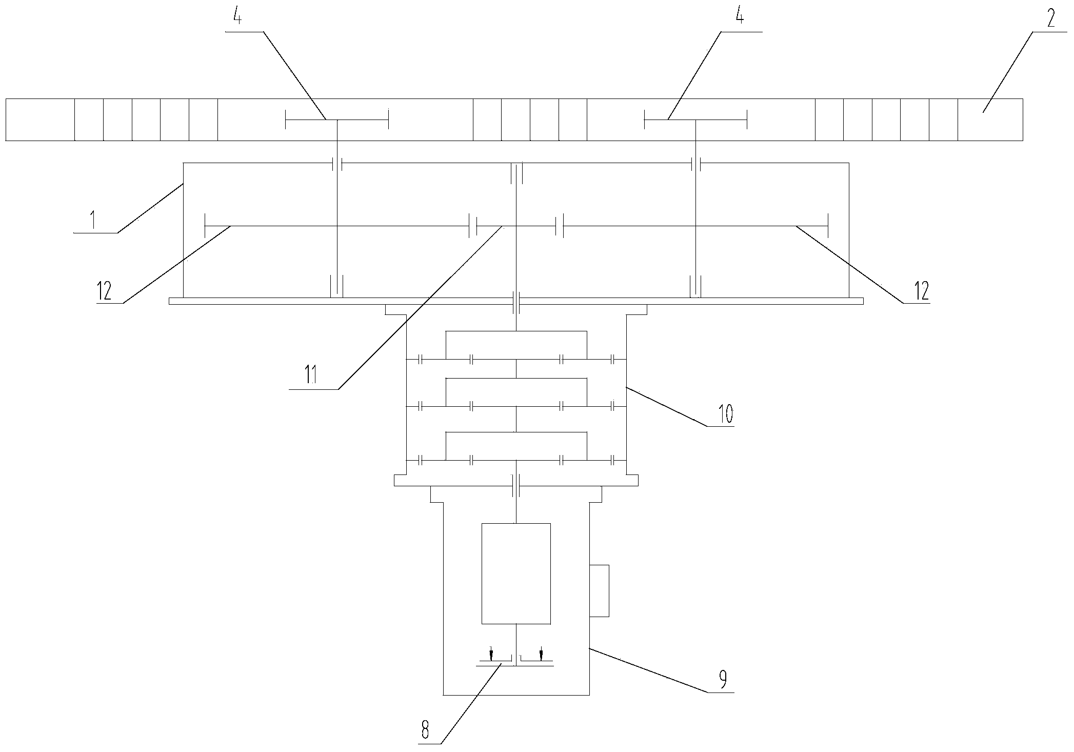
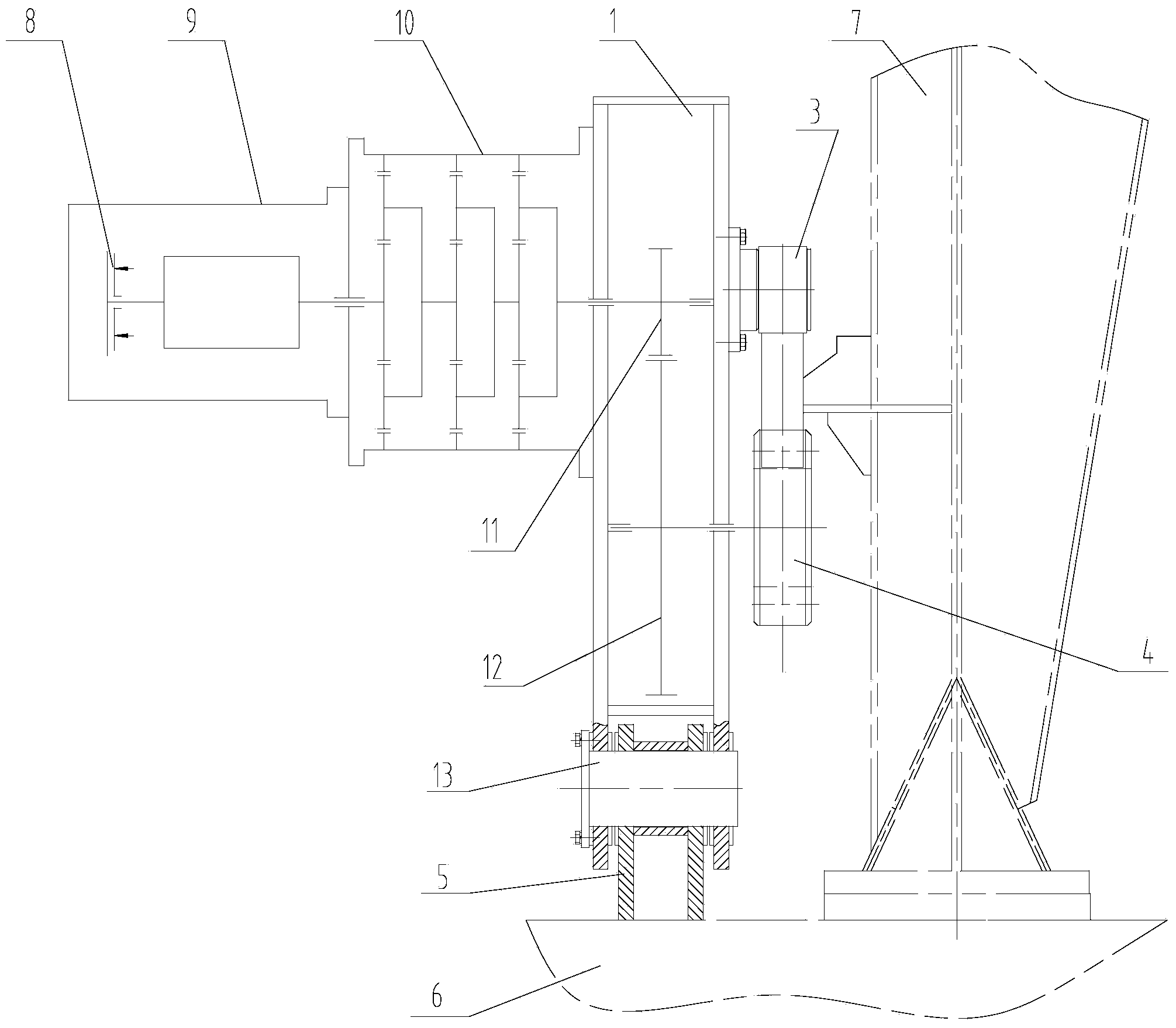
[0038] A self-elevating drilling platform cantilever beam 7 sliding device, which is installed on the main deck 6 of the platform, and is located beside the cantilever beam 7, which includes:

[0039] The multi-stage planetary reducer 10 is installed on the side of the sliding body 1, on the side opposite to the roller assembly 3 and the drive gear 4, and a power source is arranged beside the multi-stage planetary reducer 10 to drive its internal gears to rotate , the direction of rotation can be changed;

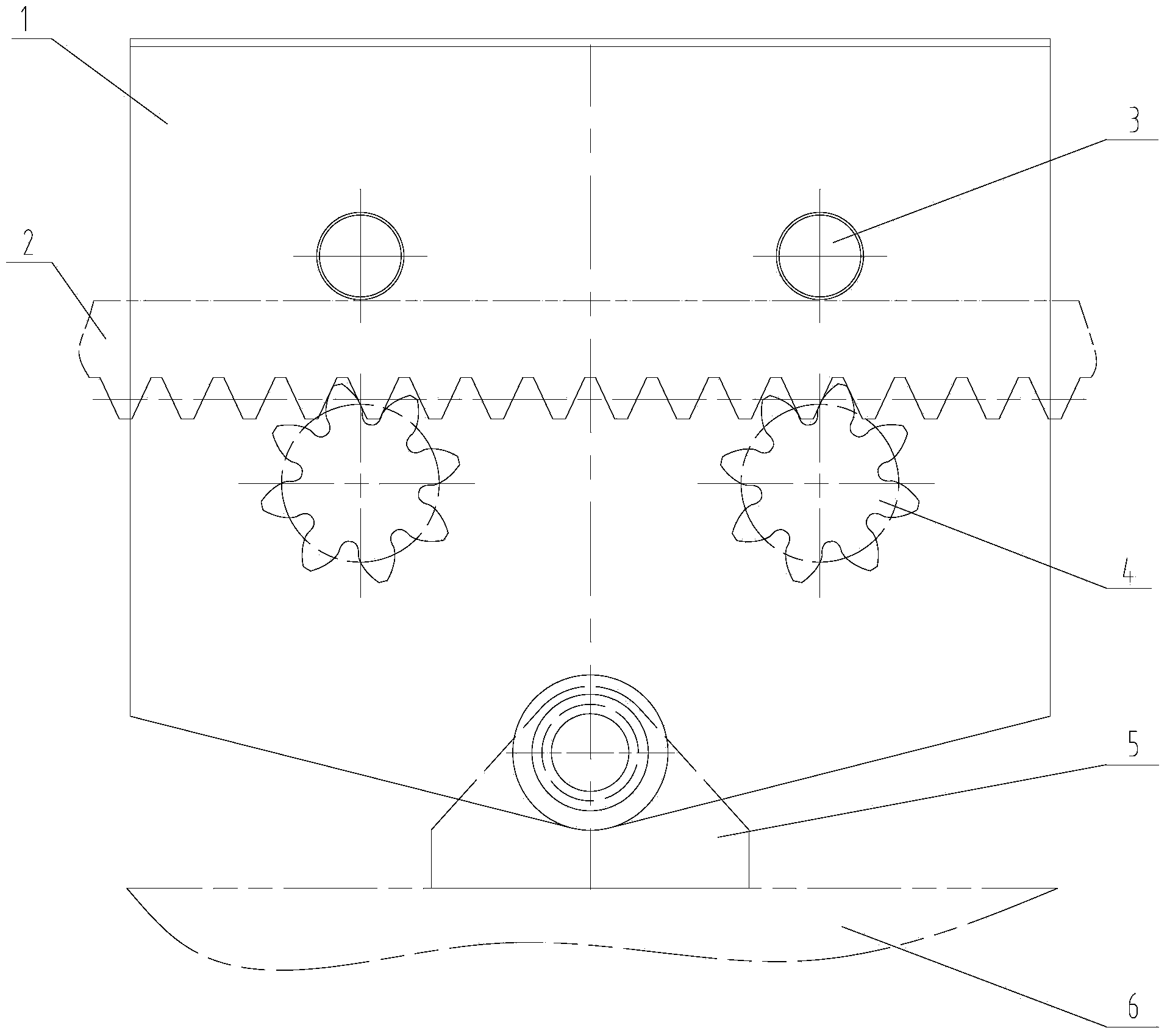
[0040] Sliding body 1, which is installed on the main deck 6 of the platform, a gear pair is arranged inside the sliding body 1, and the gear pair is connected with the output shaft of the multi-stage planetary reducer 10 and driven by it. The outside of the sliding body 1 is equipped with a driving gear 4 driven by the output shaft of the gear pair, and its number is equal to or greater than two. Above or below, a rack 2 is installed between the roller assembly 3 and the ...


PUM


Abstract

The invention relates to the field of mobile type drilling facilities, particularly to a self-elevating drilling platform cantilever beam sliding device. The self-elevating drilling platform cantilever beam sliding device comprises a multi-level planetary reducer and a sliding machine body; a power source which is arranged beside the multi-level planetary reducer drives an internal gear of the multi-level planetary reducer to rotate and the rotating direction can be changed; the sliding machine body is installed on a main deck of a platform; a gear pair is installed inside the sliding machine body; the gear pair is connected with an output shaft of the multi-level planetary reducer; the exterior of the sliding machine body is provided with a driving gear which is driven by an output shaft of the gear pair; the exterior of the sliding body is provided with a rolling wheel assembly; the rolling wheel assembly is arranged above or below the driving gear; a rack is arranged between the rolling wheel assembly and the driving gear in a flat mode; teeth on one side of the rack are engaged with the driving gear; the other side of the rack is matched with the rolling wheel assembly; the rack is fixedly connected with a cantilever beam. The self-elevating drilling platform cantilever beam sliding device has the advantages of being high in safety reliability, large in bearing capability, high in working efficiency and accurate in positioning.

Description

technical field [0001] The invention relates to the field of mobile drilling facilities, in particular to a cantilever beam sliding device of a self-elevating drilling platform. Background technique [0002] In the current offshore oil and gas exploration and development, the jack-up drilling platform is currently the most widely used mobile drilling facility. The cantilever beam sliding device is responsible for the movement and positioning of the drilling platform between different well positions in order to complete multi-well drilling operations. The design of the sliding device has always been highly valued in the design of the platform, and its performance directly affects the safety and use effect of the platform. [0003] At present, most of the cantilever beam sliding devices of jack-up drilling platforms adopt hydraulic bolt stepping sliding devices. The disadvantages of this device are: [0004] 1. Holes must be opened on the guide rail surface of the pin on the...

Claims


Application Information

Patent Timeline
Patent Type & Authority Applications(China)
IPC IPC(8): E02B17/08
CPCE02B17/00
Inventor 石会立张廷忠张泽
Owner SICHUAN HONGHUA PETROLEUM EQUIP
Why Eureka
Try Eureka