Ball valve flange combined rolled ring forming method

A technology of composite rolling and flange, applied in the direction of metal rolling, etc., can solve the problems of material consumption during cutting, asynchronous, and the surface groove cannot be formed completely.

Active Publication Date: 2015-01-07
ZHANGJIAGANG HAILU ANNULAR FORGINGS +1
View PDF4 Cites 7 Cited by
  • Summary
  • Abstract
  • Description
  • Claims
  • Application Information

AI Technical Summary

Problems solved by technology

At present, most of the ball valve flanges are pre-formed by traditional free forging or die forging, and then cut to form the cross-sectional profile. The overall forging has high energy consumption, low efficiency, high labor intensity, and poor forming accuracy, resulting in subsequent cutting man-hours and material consumption
This type of parts can also be formed by ring rolling, but due to its complex cross-sectional shape, the diameter expansion and cross-section filling are not synchronized during the ring rolling process, resulting in the surface grooves not being completely formed when the diameter reaches the desired value, and a large amount of cutting is still required.
Therefore, for ball valve flanges, whether forging or ring rolling methods are used, there are technical shortcomings such as low material utilization, low production efficiency, and high production costs, and the key parts of the groove cannot obtain sufficient plastic deformation to refine the structure and improve performance, it is necessary to develop new low-consumption, high-efficiency advanced forming methods to improve manufacturing technology and economic level and product quality

Method used


Image

  • Ball valve flange combined rolled ring forming method
  • Ball valve flange combined rolled ring forming method
  • Ball valve flange combined rolled ring forming method

Examples


Embodiment ( 1

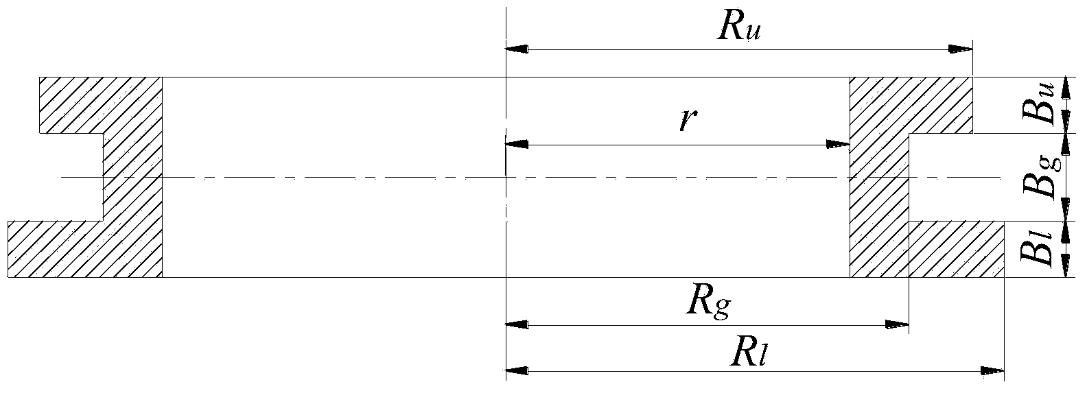
[0185] by figure 1 The ball valve flange shown is a specific example, and the upper step radius R of the rolled forging is required u , Groove radius R g , down step radius R l and the inner radius r are 728mm, 625mm, 768mm and 380mm respectively, and the height of the step on the forging is B u , groove height B g and lower step height B l They are 128mm, 176mm, and 128mm respectively. Its compound rolling ring forming method includes the following contents:

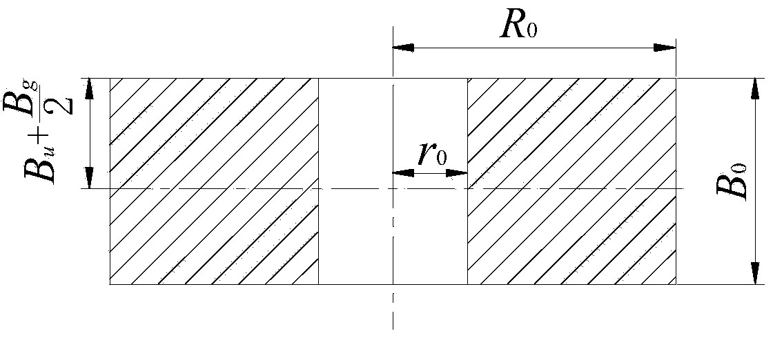
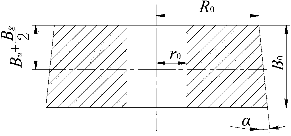
[0186] 1. Determine the shape and size of the ring blank

[0187] 1) Determine the cross-sectional shape of the ring blank. Calculate the asymmetry K of the forging according to the size of the forging s =0.3>0.15, so step ring blanks are used.

[0188] 2) Calculate the volume of the ring blank. According to the volume of the forging, the volume of the ring blank is determined as V 0 =470310947mm 3 , the ratio of the volume of the upper half of the forging to the overall forging K u =0.474, take the correct...

Embodiment ( 2

[0202] by figure 1 The ball valve flange shown is a specific example, and the upper step radius R of the rolled forging is required u , Groove radius R g , down step radius R l and the inner radius r are 90mm, 75mm, 95mm and 65mm respectively, and the height of the step on the forging is B u , groove height B g and lower step height B l They are 14mm, 26mm and 14mm respectively. Its compound rolling ring forming method includes the following contents:

[0203] 1. Determine the shape and size of the ring blank

[0204] 1) Determine the cross-sectional shape of the ring blank. Calculate the asymmetry K of the forging according to the size of the forging s =0.272>0.15, so the step ring blank is used.

[0205] 2) Calculate the volume of the ring blank. According to the volume of the forging, the volume of the ring blank is determined as V 0 =821791mm 3 , the ratio of the volume of the upper half of the forging to the overall forging K u =0.475, take the correction coe...


PUM


Abstract

The invention relates to a ball valve flange combined rolled ring forming method. The ball valve flange combined rolled ring forming method is characterized by including the following steps of (1) determining shape and size of a ring blank, (2) determining structure and size of a rolled hole and (3) determining rolled forming parameters, wherein the step (1) includes that the shape of the ring blank is determined according to geometrical characteristics of a section of a forge piece, the volume and the equivalent rolling ratio of the ring blank are determined according to geometric dimensioning of the forge piece, and the size of the ring blank is determined; the step (2) includes that working surface structures and sizes of a main roller, a core roller and an auxiliary roller are determined by combination of combined rolled ring deformation conditions, device structures and sizes of the ring blank and the forge piece; the step (3) includes that rolling line speed, rolling feeding speed and rolling time are sequentially determined by combination of sizes of the rollers, the ring blank and the forge piece and combination of combined rolled ring stable conditions and rolling process stability requirements. According to the ball valve flange combined rolled ring forming method, the rolling process is reasonably designed and controlled, a ball valve flange combined rolled ring can be accurately formed, energy materials consumption can be effectively reduced, the production efficiency is increased, and production costs are lowered.

Description

technical field [0001] The invention relates to the field of mechanical equipment manufacturing, in particular to a ball valve flange compound rolling ring forming method. Background technique [0002] Ball valve is a typical valve part, which has important applications in petroleum, chemical industry, water conservancy, electric power and other industries, and is a key basic part of energy equipment. As the key connection between the ball valve and the pipeline, the ball valve flange is an important part that affects the safety of energy transmission and storage. The surface of the ball valve flange has complex grooves composed of symmetrical or asymmetrical steps. It is a complex ring part that usually needs to be forged to ensure its mechanical properties. At present, most of the ball valve flanges are pre-formed by traditional free forging or die forging, and then cut to form the cross-sectional profile. The overall forging has high energy consumption, low efficiency, h...

Claims


Application Information

Patent Timeline
IPC IPC(8): B21H1/06
Inventor 钱东升邓加东吴剑汪小凯宋亚东戴玉同
Owner ZHANGJIAGANG HAILU ANNULAR FORGINGS
Why Eureka
Try Eureka