
Low-energy-consumption and ultraclean-emission flue gas desulfurization method and device

A desulfurization device and low energy consumption technology, which is applied in the field of flue gas pollution treatment and power plant flue gas desulfurization, can solve the problems of low quality of desulfurization by-product gypsum, low desulfurization efficiency, and high energy consumption in operation, so as to improve the purity of gypsum and improve the quality of slurry The effect of density and high desulfurization efficiency

Inactive Publication Date: 2015-01-07
DONGFANG BOILER GROUP OF DONGFANG ELECTRIC CORP
View PDF8 Cites 11 Cited by
  • Summary
  • Abstract
  • Description
  • Claims
  • Application Information

AI Technical Summary

Problems solved by technology

[0005] The object of the present invention is to propose a desulfurization method and device that has low energy consumption and can realize ultra-clean discharge of flue gas, so as to solve the problem of liquid desulfurization net flue gas carrying too high solid concentration in the existing limestone-gypsum wet flue gas desulfurization process. Dropping, low desulfurization efficiency, low quality of desulfurization by-product gypsum and high energy consumption

Method used


Image

  • Low-energy-consumption and ultraclean-emission flue gas desulfurization method and device

Examples


Embodiment Construction

[0040] The following non-limiting examples illustrate the invention.

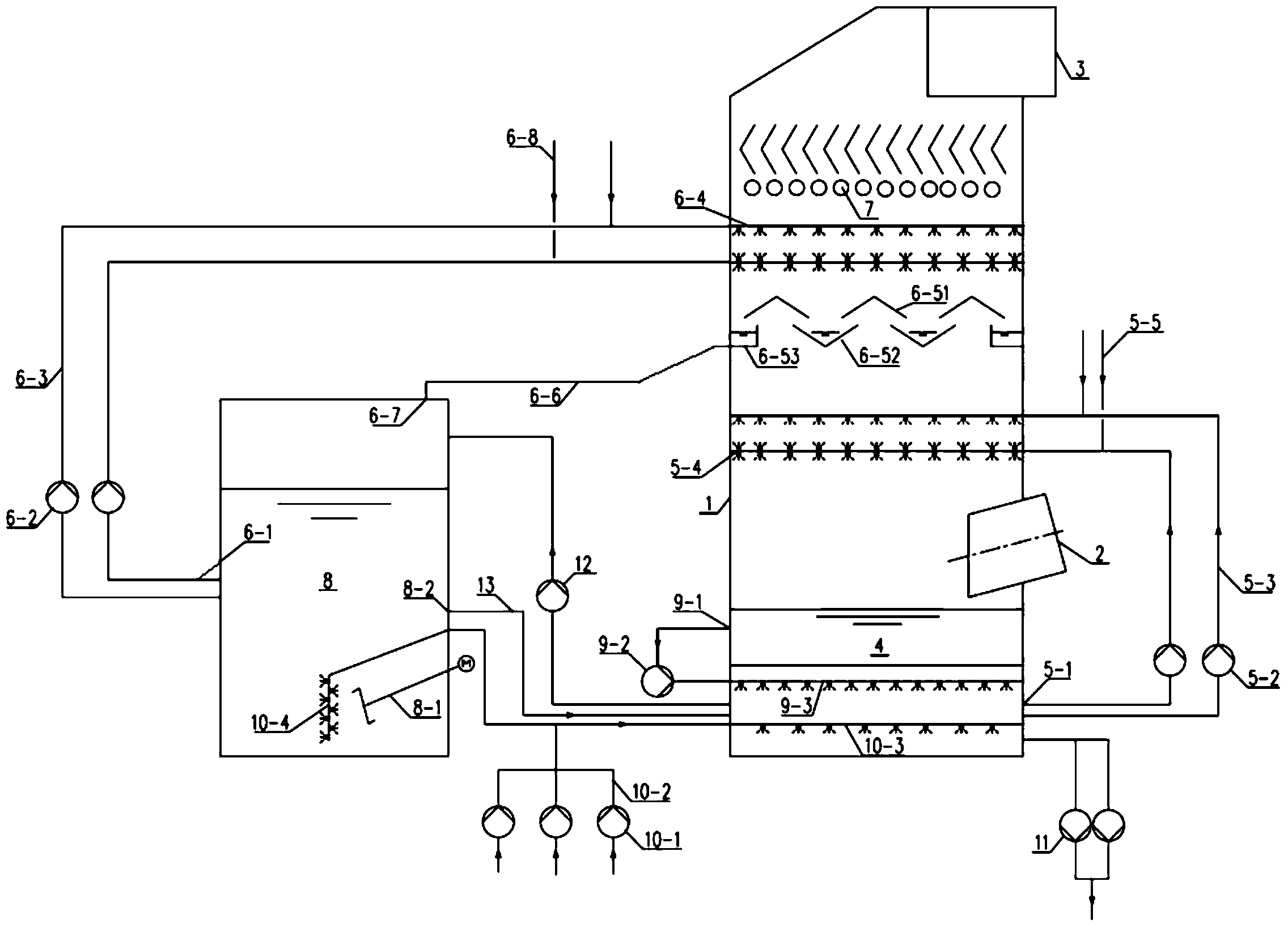
[0041] refer to figure 1 Shown:

[0042] 1. Flue gas line:

[0043] A roof-type gas-liquid splitter 6-5 is arranged between the spray layers of the absorption tower 1, and the roof-type gas-liquid splitter 6-5 is composed of a splitter ridge 6-51, a liquid collection tank 6-52 and a confluence tank 6-53, The distribution ridges 6-51 and the liquid collection grooves 6-52 are arranged in a staggered manner in the form of positive and negative mirror images. The splitter ridge 6-51 is arranged horizontally, and the liquid collection tank 6-52 and the confluence tank 6-53 are inclined toward the slurry outlet to prevent the solids in the desulfurization slurry from depositing in the liquid collection tank and the confluence tank. Angle 3-15°. The sprayed slurry forms a liquid film between the distribution ridge 6-51 and the sump 6-52.

[0044] The flue gas enters the absorption tower 1 from the flue gas i...


PUM

PropertyMeasurementUnit
densityaaaaaaaaaa
densityaaaaaaaaaa

Abstract

The invention discloses a low-energy-consumption and ultraclean-emission flue gas desulfurization method and device and belongs to the field of flue gas pollution treatment. According to the invention, desulfurization slurry is divided into two independent desulfurization spraying slurry circulating systems and a three-circulation desulfurization process of a double-slurry collection device (a slurry tank / box), double-slurry density and control of pH values of slurry of different regions is adopted so that the aims of lowering energy consumption and meeting the requirements of ultraclean or near-zero emission of PM and SO2 are realized. The double-slurry tank / box is arranged, the different slurry densities of the double-slurry tank / box is controlled, the pH values of the slurry in the different regions are controlled and the two independent slurry circulating systems are formed, so that the aims that the solid content of desulfurized pure flue gas liquid drops is lower than 10% and the system desulfurization efficiency is more than 99% are realized; and a slurry tank outside a tower is arranged at a high liquid level and fewer spraying layers are arranged so that the aims of lowering the power of a circulating pump and reducing the operation power consumption of the desulfurization are realized.

Description

technical field [0001] The invention belongs to the field of flue gas pollution treatment, in particular to the field of power plant flue gas desulfurization. Background technique [0002] Wet flue gas desulfurization technology has been widely used in the field of flue gas desulfurization in thermal power plants due to its mature process, high desulfurization efficiency, and low investment and operating costs. Among them, the limestone-gypsum wet flue gas desulfurization process occupies more than 90% of the market share of flue gas desulfurization in thermal power plants in my country due to its early development, mature and reliable technology, and cheap and easy-to-obtain desulfurizer raw materials. At present, the desulfurization efficiency of the existing limestone-gypsum wet flue gas desulfurization process can usually reach more than 95%. [0003] Under the guidance of national policies, the flue gas pollutants of thermal power plants are moved closer to ultra-clean...

Claims


Application Information

Patent Timeline
Patent Type & Authority Applications(China)
IPC IPC(8): B01D53/80B01D53/50B01D53/96C01F11/46
Inventor 杨志忠李元崔有贵邓毅
Owner DONGFANG BOILER GROUP OF DONGFANG ELECTRIC CORP
Learn More