
Single-rotation double duty cycle adjustable circuit

A single-rotation dual-duty cycle technology, applied to electrical components, electric pulse generation, pulse technology, etc., can solve problems such as increased noise, local oscillator leakage, and inability to correct the duty cycle, achieving the effect of simple structure

Active Publication Date: 2017-07-04
CHENGDU CORPRO TECH CO LTD
View PDF3 Cites 0 Cited by
  • Summary
  • Abstract
  • Description
  • Claims
  • Application Information

AI Technical Summary

Problems solved by technology

[0003] However, in RF front-end applications, if the prescaler using the TSPC structure is divided by an odd number, the duty cycle of the signal generated by the prescaler is not 50%, and it is a single-ended output
After a simple single-ended to differential device, the duty cycle cannot be corrected
When the duty cycle of the input signal of the mixer is not 50%, problems such as local oscillator leakage and noise increase will occur

Method used


Image

  • Single-rotation double duty cycle adjustable circuit
  • Single-rotation double duty cycle adjustable circuit

Examples


Embodiment Construction

[0016] The technical solution of the present invention will be further described in detail below in conjunction with the accompanying drawings, but the protection scope of the present invention is not limited to the following description.

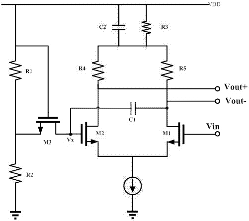
[0017] Such as figure 1 As shown, the single-rotation dual-duty-cycle adjustable circuit includes a first differential pair of tubes M1, a second differential pair of tubes M2 and an inverse proportional tube M3. The gate of the first differential pair of tubes M1 is connected to the input signal V in , the drain of the first differential pair transistor M1 is connected to the gate of the second differential pair transistor M2 through a DC blocking capacitor C1, the drain of the second differential pair transistor M2 and the drain of the first differential pair transistor M1 are differential output terminals, and the second differential pair transistor M1 is a differential output terminal. The source of a differential pair transistor M1 and...


PUM


Abstract

The invention relates to a singe-end-to-dual-end duty-ratio-adjustable circuit which comprises a first differential pair transistor M1, a second differential pair transistor M2 and a reverse proportion transistor M3. A grid electrode of the first differential pair transistor M1 is connected with an input signal, a drain electrode of the first differential pair transistor M1 is connected with a grid electrode of the second differential pair transistor M2 through a blocking capacitor C1, a drain electrode of the second differential pair transistor M2 and the drain electrode of the first differential pair transistor M1 are adopted as differential output ends, and a source electrode of the first differential pair transistor M1 and a source electrode of the second differential pair transistor M2 are both connected with a current source. A grid electrode of the inverse proportion transistor M3 is connected with a supply voltage, a drain electrode of the inverse proportion transistor M3 is connected with the grid electrode of the second differential pair transistor M2, and a source electrode of the inverse proportion transistor M3 is connected with the middle point of a bleeder circuit formed by the an R1 and an R2. Through the singe-end-to-dual-end duty-ratio-adjustable circuit, differential output and duty ratio adjustment can be achieved at the same time, and the structure is simple. The value of the R1 and the value of the R2 are set, and the duty ratio of an output waveform can be adjusted to 50 percent.

Description

technical field [0001] The invention relates to a differential circuit, in particular to a single-rotation double-duty ratio adjustable circuit. Background technique [0002] In a communication system, in order to improve the noise resistance, the RF front-end circuit of the receiver generally adopts a differential structure, and the single-ended signal is converted into a differential signal through a single-ended to differential device. As described in patent application number 2012100461973, the single-ended to double-ended circuit includes a first transistor, a second transistor and a transformation unit, the transformation unit includes a first inductance element, a second inductance element and a third inductance element, the first An inductance element and a third inductance element perform a first coupling according to a first mutual coupling parameter, and a second inductance element and a third inductance element perform a second coupling according to a second mutu...

Claims


Application Information

Patent Timeline
Patent Type & Authority Patents(China)
IPC IPC(8): H03K3/017
Inventor 陶健邵志刚
Owner CHENGDU CORPRO TECH CO LTD
Learn More