Automatic transmission controller

A technology for automatic transmissions and control devices, which is applied to transmissions, gear transmissions, transmission controls, etc., can solve problems such as cost issues, and achieve the effects of reducing weight, suppressing shifting shocks, and improving responsiveness

Active Publication Date: 2014-12-24
HONDA MOTOR CO LTD
View PDF9 Cites 11 Cited by
  • Summary
  • Abstract
  • Description
  • Claims
  • Application Information

AI Technical Summary

Problems solved by technology

[0009] However, the above-mentioned prior arts all require a sensor for detecting the inclination angle of the parking position, which causes a problem in terms of cost.
[0010] In addition, the technical idea of ​​the prior art of the above-mentioned document 2 does not rely on an additional hardware sensor, but rather uses the control method in the automatic transmission to avoid backing. For this reason, the control logic for detecting the backing itself (document 1) is set, or it is set only in Complicated control logic such as permitting idle stop control under the condition of not performing reverse (brake pressure, etc.)

Method used


Image

  • Automatic transmission controller
  • Automatic transmission controller
  • Automatic transmission controller

Examples


no. 2 Embodiment approach

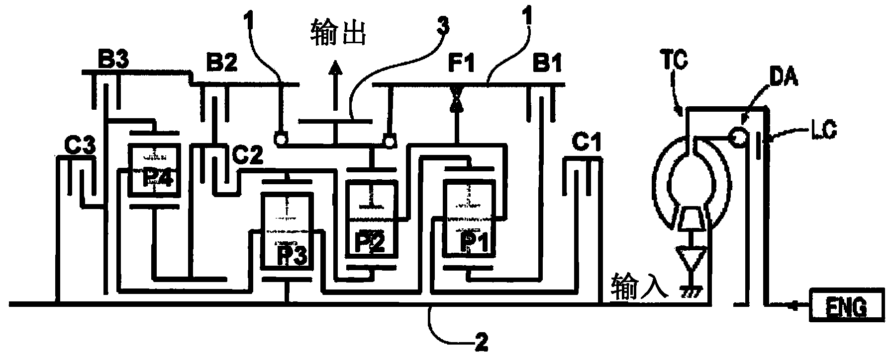
[0133] Since the above-mentioned first embodiment includes the electric pump, the clutch and the brake can be hydraulically controlled by using the electric pump even when the engine is stopped. The second embodiment includes a pressure accumulator instead of the electric pump. The accumulator is a mechanical pressure accumulating device. When the engine is running, the oil pressure is stored in the accumulator tank, and it is maintained when the engine is idle and turned off. When it is restored, the accumulated oil pressure is taken out for use.

[0134] according to Figure 9B The control procedure of the following describes the control flow of the second embodiment. Step 30 , step 32 , step 42 , and step 44 are equivalent to checking that the condition of the idle stop control is satisfied. That is, when the engine is not stopped and the vehicle speed is greatly reduced without returning from the idle stop control, the process proceeds from step 44 to step 46, engages cl...

Deformed example 1

[0143] It also serves the purpose of filling ATF (ineffective filling) in the oil passage for recovery from idling cutoff, and enables early idling cutoff engagement (C2 / B2: engagement) at low vehicle speeds before stopping in D range.

[0144]

[0145] No oil pressure is supplied during idling cut-off, and when returning from idling cut-off control, the linear solenoid valve for C2 / B2 control is fully opened, and C2 / B2 is engaged immediately. Thereby, it is possible to reliably avoid backing up. That is, it is because the oil pressure of C2 / B2 is accumulated by a normal engine-driven oil pump.

Deformed example 2

[0147] In the second embodiment, at the time of return from idling stop, the return from idling stop determination signal is received, and the accumulated pressure is supplied to the linear solenoid valve for B1 pressure control in advance. This achieves the effect of speeding up the response time for shifting gears.

[0148] Therefore, in the case of returning from idling-off engagement, when the internal rotational speed of the transmission is almost 0 rpm during parking, the brake B1 can be engaged by fully opening the linear solenoid valve for brake B1 control, and the return from idling-off engagement can be performed. The spindle speed remains at 0.

[0149]

[0150] In the second embodiment, as in the first embodiment, the transition from the idle stop engagement to the first speed is performed by switching C2 and B1 while the brake B2 is engaged. At this time, the pressure of the clutch C2 remains in a non-backward manner, and when the pressure of the brake B1 of th...


PUM


Abstract

An automatic transmission controller for controlling an automatic transmission includes an idling reduction controller, an idling-reduction-control permission determiner, and an engagement controller. The idling-reduction-control permission determiner is configured to determine whether or not to permit an idling reduction control. The engagement controller, in a case where the idling-reduction-control permission determiner permits the idling reduction control, is configured to allow rotation of an input shaft of an automatic transmission, and in a case where an output shaft of the automatic transmission is rotated by a wheel of a vehicle in a rotational direction such that the vehicle moves backward, is configured to set a plurality of engagement mechanisms including at least a mechanical engagement mechanism so as to fix the output shaft of the automatic transmission to a casing of the automatic transmission or so as to prevent the vehicle from moving backward.

Description

technical field [0001] The present invention relates to a control device for controlling an automatic transmission using a planetary gear mechanism, and in particular to an improvement in technology for preventing unintended rollback of a vehicle due to slopes or the like when returning to normal control from a so-called "idle stop control" state. Background technique [0002] In order to improve driving performance and driving performance, automatic transmissions of automobiles are developing multi-speed gears. An automatic transmission generally has an engagement mechanism such as a planetary gear mechanism and a clutch and a brake, and each gear stage is realized by switching a power transmission path using the engagement mechanism. Furthermore, such an automatic transmission interposes a torque converter (starting mechanism) provided between the drive source and the drive wheels in order to transmit rotational power from the drive source to the drive wheels of the vehicl...

Claims


Application Information

Patent Timeline
Patent Type & Authority Applications(China)
IPC IPC(8): F16H59/02F16H59/74F16H61/02F16H61/04F16H61/20F16H63/34
CPCF16H3/666F16H2200/2082F16H2200/0069F16H2200/2012F16H2200/2046B60W10/06B60W10/115B60W30/18054B60W30/18118B60W2510/0642B60W10/10
Inventor 橘田祐也石川丰
Owner HONDA MOTOR CO LTD
Why Eureka
Try Eureka