
Hydraulic Control Main Valve for Energy Regeneration

A hydraulic and energy technology, applied in the direction of fluid pressure actuators, servo motor components, mechanical equipment, etc., can solve problems such as piston stalling and falling, cylinder rod chamber insufficient oil supply, etc.

Active Publication Date: 2017-02-15
JIANGSU HENGLI HYDRAULIC TECH CO LTD
View PDF6 Cites 0 Cited by
  • Summary
  • Abstract
  • Description
  • Claims
  • Application Information

AI Technical Summary

Problems solved by technology

[0002] During the use of the hydraulic control main valve in the prior art, when the spool is switched to the R position: during the downward movement of the piston, the piston will be accelerated downward by the mechanism and the gravity of the material. On the one hand, the piston cavity On the other hand, when the downward movement is accelerated, the flow of p to the rodless chamber cannot be satisfied in time, which will cause the unfavorable phenomenon that the piston stalls and falls and the rod chamber of the cylinder is insufficiently replenished to form a vacuum

Method used


Image

  • Hydraulic Control Main Valve for Energy Regeneration
  • Hydraulic Control Main Valve for Energy Regeneration
  • Hydraulic Control Main Valve for Energy Regeneration

Examples


Embodiment 1)

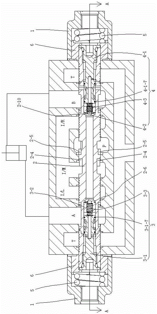
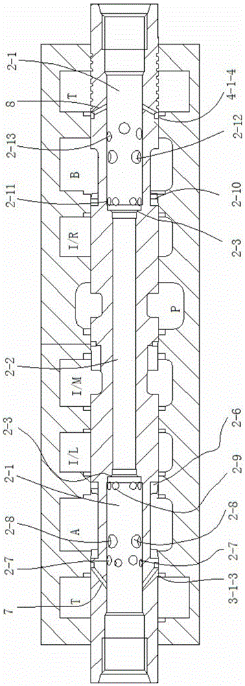
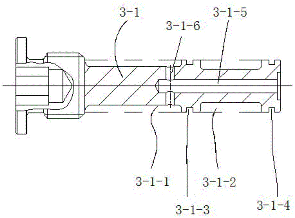
[0023] See figure 1 , a hydraulically controlled main valve for energy regeneration and utilization, has an end cover 1, a valve core 2, a left check valve 3 and a right check valve 4; There are left oil port T, oil port A, oil port I / L, oil port I / M, oil port I / R, oil port B, right oil port T and oil port P; There are springs 5 ​​and spring seats 6 between them; the left and right ends of the valve core 2 are respectively embedded with a left check valve 3 and a right check valve 4; the left check valve 3 is composed of a left valve seat 3-1, a left cone valve core 3-2 and the left spring 3-3; the conical surface of the left cone spool 3-2 is closely attached to the left conical surface of the spool 2 through the action of the left spring 3-3; the right one-way valve 4 is formed by the right valve seat 4-1, right cone spool 4-2 and right spring 4-3 are formed; the cone surface of right cone spool 4-2 is close to the right cone surface of spool 2 by the effect of right spring...


PUM


Abstract

The invention relates to a hydraulic-control main valve for energy recycling. The hydraulic-control main valve comprises end caps, a valve spool, a left check valve and a right check valve, one end cap is arranged at each end of the valve spool, and a left oil port T, an oil port A, an oil port I / L, an oil port I / M, an oil port I / R, an oil port B, a right oil port T and an oil port P are arranged on the valve spool; a spring and a spring seat are arranged between each end cap and the valve spool; the left check valve and the right check valve are embedded in the left and right ends of the valve spool respectively; the left check valve is composed of a left valve seat, a left cone valve spool and a left spring seat; the conical surface of the left cone valve spool clings to the left conical surface of the valve spool under the action of the left spring; the right check valve is composed of a right valve seat, a right cone valve spool and a right spring; the conical surface of the right cone valve spool clings to the right conical surface of the valve spool under the action of the right spring. By the hydraulic-control main valve, dropping speed of a piston can be limited, potential energy on the piston under the gravity action of a mechanism and materials is utilized, and energy recycling is realized.

Description

technical field [0001] The invention relates to a hydraulically controlled main valve, in particular to a hydraulically controlled main valve for energy regeneration. Background technique [0002] During the use of the hydraulic control main valve in the prior art, when the spool is switched to the R position: during the downward movement of the piston, the piston will be accelerated downward by the mechanism and the gravity of the material. On the one hand, the piston cavity On the other hand, when accelerating downward, the flow of p to the rodless chamber cannot be satisfied in time, which will cause the unfavorable phenomenon that the piston stalls and falls and the rod chamber of the cylinder is insufficiently replenished to form a vacuum. Contents of the invention [0003] The purpose of the present invention is to overcome the defects of the prior art and provide a hydraulically controlled main valve that can limit the falling speed of the piston and utilize the pot...

Claims


Application Information

Patent Timeline
Patent Type & Authority Patents(China)
IPC IPC(8): F15B13/02
Inventor 汪立平卢强陈展刘红光张国良
Owner JIANGSU HENGLI HYDRAULIC TECH CO LTD
Learn More