A plunger pump power control device and control method thereof

A technology of power control and plunger pump, which is applied in the direction of pump control, liquid variable displacement machinery, machine/engine, etc., can solve the problems of variable variable jamming, etc., and achieve the effect of variable variable, simple structure, and small error

Active Publication Date: 2016-08-17
JIANGSU HENGLI HYDRAULIC TECH CO LTD
View PDF8 Cites 0 Cited by
  • Summary
  • Abstract
  • Description
  • Claims
  • Application Information

AI Technical Summary

Problems solved by technology

Due to the coaxial error of the diameter of the two steps of the valve sleeve and the valve core, there is an objective existence, so variable jamming will occur

Method used


Image

  • A plunger pump power control device and control method thereof
  • A plunger pump power control device and control method thereof
  • A plunger pump power control device and control method thereof

Examples


Embodiment 1

[0029] (Example 1, a plunger pump power control device)

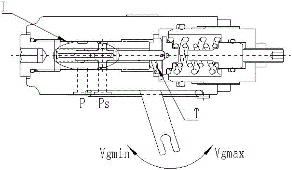
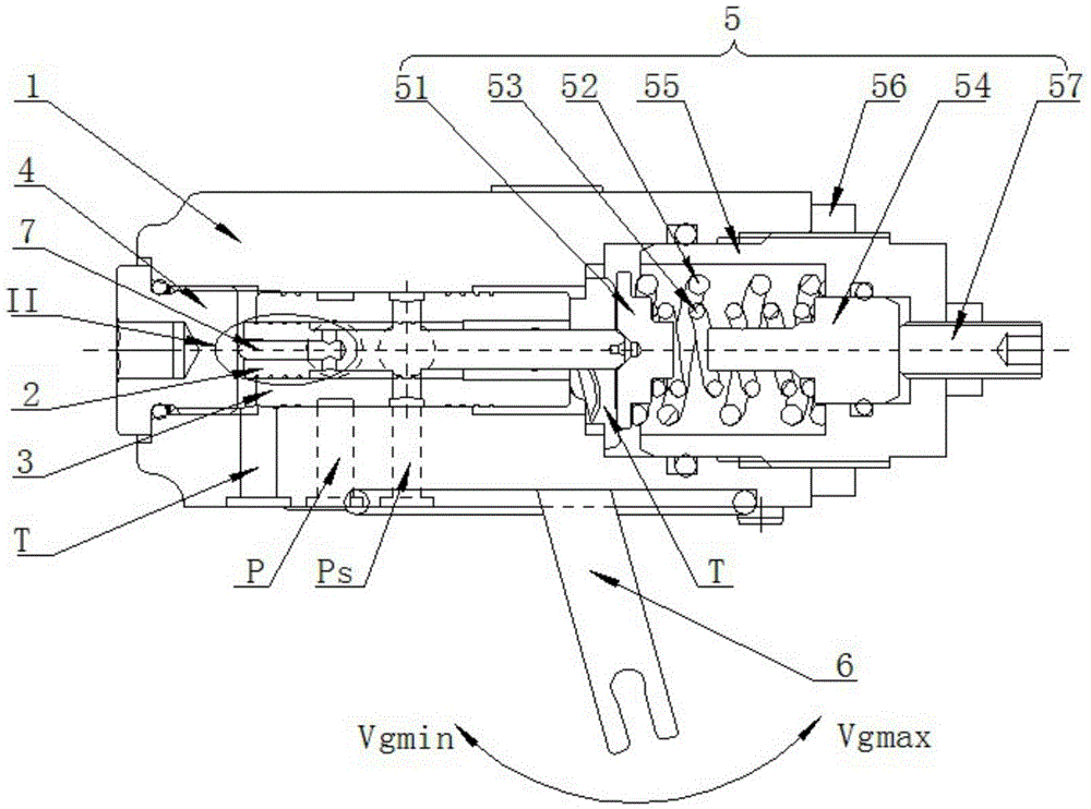
[0030] See Figure 3 to Figure 5 , a plunger pump power control device, with a control valve body 1, a valve core 2, a valve sleeve 3, a stop screw plug 4, a spring preload mechanism 5, a feedback mechanism 6 and a slide valve 7; the control valve body 1 is provided with There are oil inlet P, oil outlet Ps and two oil discharge ports T; the oil outlet Ps is externally connected to the variable piston chamber of the pump body; the valve core 2 is set in the valve sleeve 3, and the valve sleeve 3 and the valve core 2 form a 3-position 2-way structure valve, the E chamber is formed between the valve sleeve 3 and the valve core 2; the slide valve 7 is arranged at the center of one end of the valve core 2, and the slide valve 7 and the valve core 2 form a C cavity in the radial direction of the valve core 2, and the slide valve 7 The ball end of the ball is in contact with the stop screw plug 4; the stop screw plug 4 is se...

Embodiment 2

[0035] (Example 2, a control method for a plunger pump power control device)

[0036] A control method for a plunger pump power control device, the specific steps are as follows:

[0037] ① Set the value of the spring preload mechanism 5;

[0038]②Introduce the pressure oil at the pump outlet from the oil inlet P, and enter the cavity C of the valve core 2 through the valve sleeve 3. The pressure oil at the pump outlet pushes the slide valve 7 and the valve core 2 to move in the opposite direction, and the slide valve is stopped by the stop screw. If it is blocked, the spool moves to the compression spring preloading mechanism; or the pressure of oil inlet P decreases, and the spring preloading mechanism pushes the spool to move in the opposite direction against the pressure of cavity C;

[0039] ③ Perform binary processing, when the outlet pressure of the pump introduced into chamber C increases and exceeds the value set by the spring preload mechanism 5, the spool 2 moves i...


PUM


Abstract

The invention relates to a power control device of a plunger pump and a control method thereof, comprising a control valve body, a valve core, a valve sleeve, a stop screw, a spring preloading mechanism, a feedback mechanism and a slide valve; Oil port P, oil outlet Ps and 2 oil drain ports T; the valve core is arranged in the valve sleeve, the valve sleeve and the valve core form a 3-position 2-way structure valve, and the E cavity and the E cavity are formed between the valve sleeve and the valve core Long-pass oil inlet P; the slide valve is arranged at the center of one end of the valve core, the slide valve and the valve core form a C cavity in the radial direction of the valve core, and the spherical end of the slide valve is in contact with the stop screw; the stop screw is set at One end of the control valve body; the spring preloading mechanism is arranged on the other end of the control valve body; the valve sleeve, the valve core and the slide valve are arranged between the stop screw and the spring preloading mechanism; the feedback mechanism is hinged on the control valve body. The invention can realize the control of the output power of the hydraulic plunger pump, the power output curve of the pump is simulated by two broken lines, and the error is small; the valve core is flexibly loaded by the pressure of the C cavity.

Description

technical field [0001] The invention relates to the technical field of mechanical manufacturing, in particular to a plunger pump power control device and a control method thereof. Background technique [0002] Power control is a common control method for hydraulic pumps. Its characteristic is that within a certain working pressure range, the output power of the pump is kept constant through power control, that is, W=PQ. This kind of control is to adjust the pump outlet pressure oil into the variable piston through the power control device or remove the pressure oil from the variable piston through the power control device to push the servo piston to move to realize the change of pump displacement. The feedback lever of the power control device moves in the opposite direction until the adjustment of the power control device is closed, and the pump variable process is completed. [0003] figure 1 It is a kind of power control that is protected by intellectual property rights...

Claims


Application Information

Patent Timeline
Patent Type & Authority Patents(China)
IPC IPC(8): F04B49/22
Inventor 汪立平李童华海铭林大超韦磊
Owner JIANGSU HENGLI HYDRAULIC TECH CO LTD
Why Eureka
Try Eureka