
Discrete combination type arm frame for super-large centrifugal machine

A centrifuge and discretization technology, applied in the field of centrifuge boom, can solve the problems of increased development cost, increased cost, large radial area, etc., and achieves the effects of decentralized processing and transportation, reduced development cost, and reduced load waste.

Active Publication Date: 2014-12-24
GENERAL ENG RES INST CHINA ACAD OF ENG PHYSICS
View PDF4 Cites 10 Cited by
  • Summary
  • Abstract
  • Description
  • Claims
  • Application Information

AI Technical Summary

Problems solved by technology

[0007] Since the force-bearing structure of the tension belt of the traditional centrifuge is integral, with the increase of the effective radius and capacity of the centrifuge, the arm structure size of the ultra-large centrifuge can reach more than 20 meters, and the overall mass can exceed 200t. It is made of high-strength alloy steel. The forged tension belt not only requires the use of large-tonnage forging equipment, but also has high requirements for material quality, which leads to a low pass rate of large forgings; Difficulty and on-site installation are difficult, and the development cost doubles
In addition, the radial cross-sectional area (or width) of the traditional tension belt is the same at different parts of its length direction, but the actual force of the tension belt is different at different parts of its length direction. In order to meet the bearing requirements of the maximum force, The radial area (or width) of other less stressed parts of the tension band is also larger, resulting in material waste and increased cost, and also increases more costs for transportation and installation

Method used


Image

  • Discrete combination type arm frame for super-large centrifugal machine
  • Discrete combination type arm frame for super-large centrifugal machine
  • Discrete combination type arm frame for super-large centrifugal machine

Examples


Embodiment Construction

[0022] The present invention will be further explained below in conjunction with the drawings:

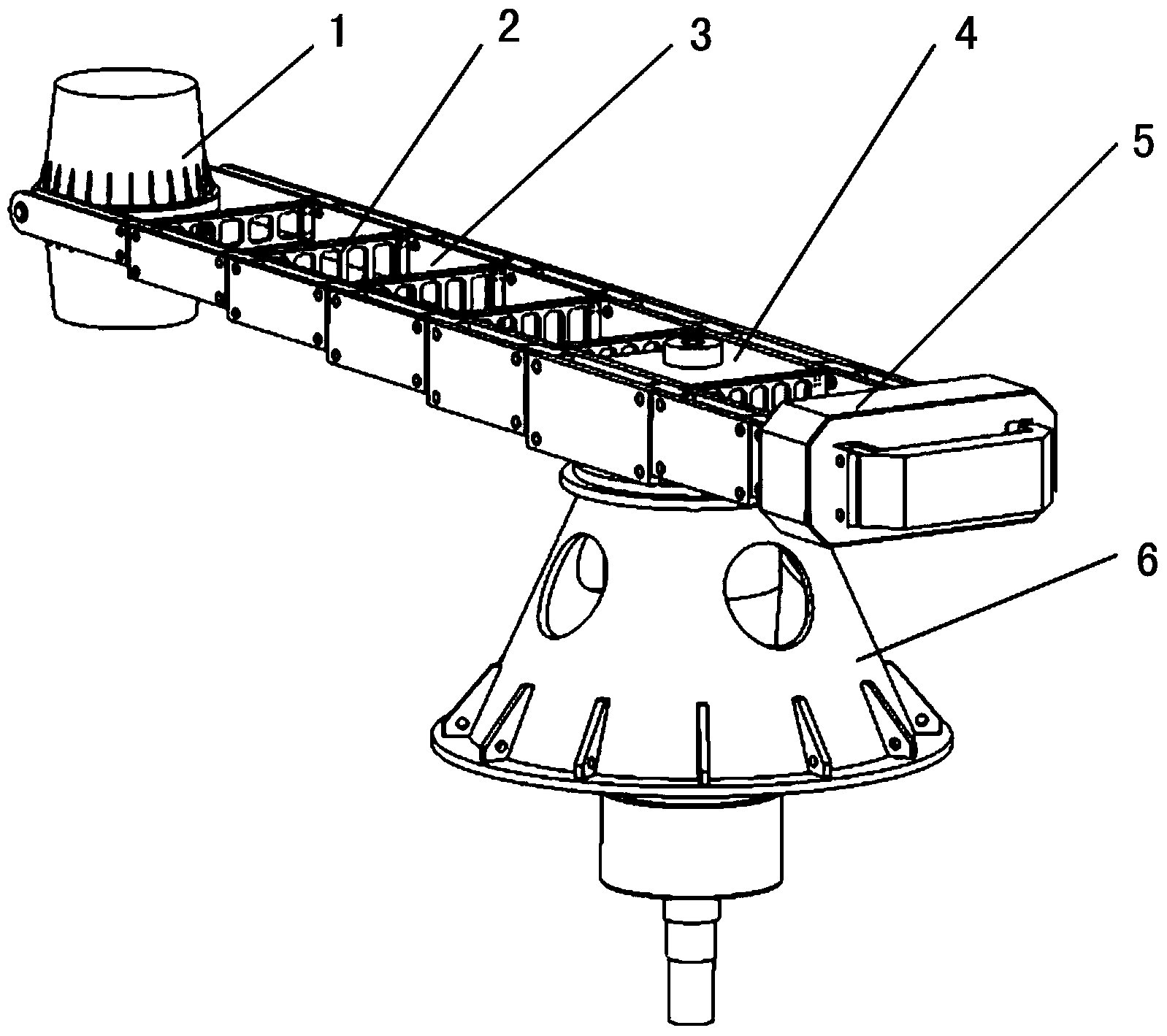
[0023] Such as figure 1 As shown, the discrete combined boom of the ultra-large centrifuge of the present invention includes two tension belts 3 and a plurality of parallel and spaced connecting plates 2 connected between the two tension belts 3. A rotating arm support plate 4 is installed in the middle section. The rotating arm support plate 4 is used to connect the boom and the main shaft (not marked in the figure); in order to facilitate the overall understanding of the centrifuge, figure 1 The bell 6 for supporting the boom, the hanging basket 1 and the counterweight 5 for balancing are also shown in the boom. The main shaft drives the boom through the rotating arm support plate 4, and the boom drives the gondola 1 and the counterweight 5 to rotate. The gondola 1 is equipped with experimental specimens, and various centrifugal experimental data are collected during the rotation of ...


PUM


Abstract

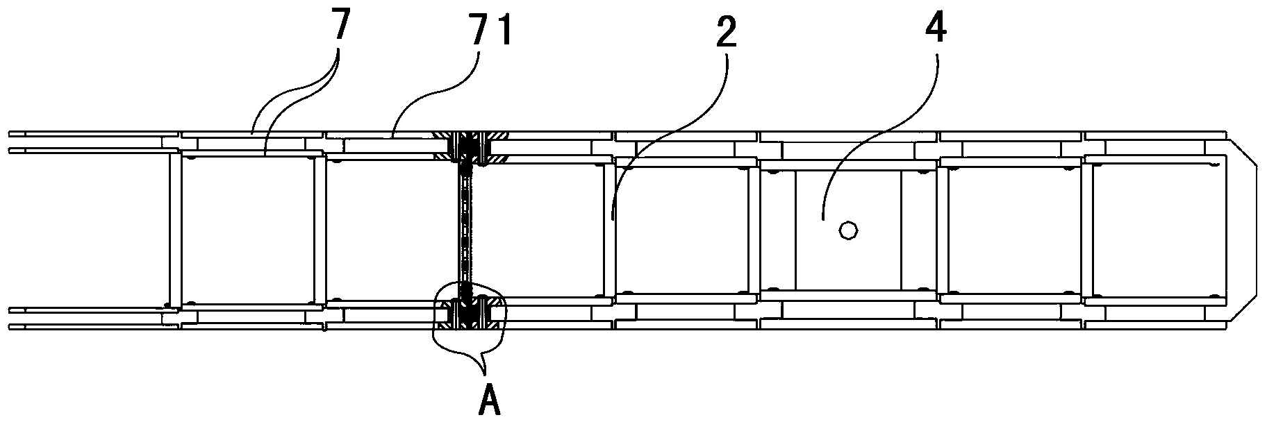
The invention discloses a discrete combination type arm frame for a super-large centrifugal machine. The discrete combination type arm frame comprises two pull straps and a plurality of connecting plates connected between the two pull straps, wherein the connecting plates are parallel to each other and are arranged at intervals; a rocker arm bearing plate is mounted at the middle section of the pull straps; each pull strap is formed by connecting a plurality of pull strap modules through connecting pieces; the radial cross-sectional areas of the different pull straps modules are the same or different; the radial cross-section areas of the pull straps from the rocker arm bearing plate as the middle part to the two end heads are respectively of a ladder-like gradually reduced structure. The pull straps are designed into modular structures, and differentiated design is carried out on the radial cross-sectional areas of the different pull strap modules, so that discrete processing and transportation are realized, the field assembly is convenient, the feasibility for manufacturing, transportation and application is improved, the load waste is reduced, the materials are reduced, the development cost is reduced, and the gross weight of the whole arm frame is reduced under the precondition of meeting the application requirements of the arm frame for the super-large centrifugal machine.

Description

Technical field [0001] The invention relates to a centrifuge arm frame, in particular to a discrete combined arm frame of an ultra-large centrifuge. Background technique [0002] Centrifuge is an important scientific test device that uses rotating centrifugal force to simulate the acceleration environment of a specific supergravity field. It is widely used in basic research and products in the fields of aviation, aerospace, navigation, weapons, transportation, water conservancy, medical treatment, energy, and geophysics. Research and development provide important research methods for the development of national defense construction, scientific research, and national economic construction. [0003] The main load of the centrifuge is the centrifugal force generated by the hanging basket, test piece and counterweight in the rotating system under a centrifugal field of up to hundreds of g. The centrifugal force of several thousand tons is completely borne by the rotating arm system, a...

Claims


Application Information

Patent Timeline
Patent Type & Authority Applications(China)
IPC IPC(8): B04B15/00
Inventor 陈刚吴文凯黄湛洪建忠陈磊罗昭宇
Owner GENERAL ENG RES INST CHINA ACAD OF ENG PHYSICS
Learn More