
Fuel nozzle

A technology of fuel nozzles and fuel oil, which is applied in the direction of fuel injection devices, engine components, machines/engines, etc. It can solve the problems of affecting the engine power index, the effect of preheating is not obvious, and the heat loss is large, so as to protect the normal operation and weight. Effect of lightness, combustion efficiency improvement

Inactive Publication Date: 2014-12-17
HARBIN DONGAN ENGINE GRP
View PDF7 Cites 1 Cited by
  • Summary
  • Abstract
  • Description
  • Claims
  • Application Information

AI Technical Summary

Problems solved by technology

However, since the preheated fuel has to pass through the filter, the distance between the preheating device and the fuel injection nozzle is too large, the structure is relatively complicated, the mass is large, and the heat loss is also relatively large, so the effect of preheating is not good. Obviously, it affects the power index of the engine

Method used


Image

  • Fuel nozzle

Examples


Embodiment Construction

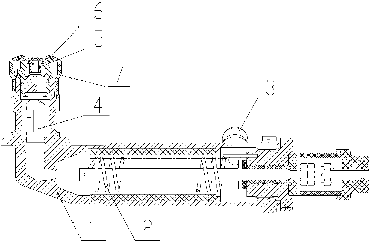
[0007] As shown in the figure, the fuel nozzle includes a housing 1, a fuel preheating device, an oil filter 4 and a fuel injection device 5. The fuel preheating device, oil filter 4 and fuel injection device 5 are sequentially installed on the housing, and the fuel The preheating device includes an oil supply joint 3 and a resistance wire 2. The oil supply joint 3 is located on the casing 1, and an oil circuit is arranged inside and communicated with the interior of the casing 1. The resistance wire 2 is located inside the casing 1, and one end of the resistance wire 2 is located at the supply The oil joint 3 is at the position, and the other end is set at the position where the oil filter 4 is installed; the fuel injection device 5 is set at the end of the housing, and the fuel directly enters the fuel injection device 5 after passing through the oil filter 4 . The fuel injection device 5 is provided with an outer casing nut 6 , and the outer casing nut 6 is provided with an ...


PUM


Abstract

The invention relates to a fuel nozzle. The fuel nozzle is characterized by comprising a shell, a fuel preheating device, an oil filter and an oil spray device, wherein the fuel preheating device, the oil filter and the oil spray device are sequentially installed on the shell, an oil circuit is arranged inside the fuel preheating device and communicated with the inside of the shell, a resistance wire is arranged inside the shell, the oil spray device is arranged on the end part of the shell, and fuel directly enters the oil spray device after passing by the oil filter. The fuel nozzle is simple and compact in structure, has characteristics of small size and light weight and is small in heat loss and also capable of effectively improving the combustion efficiency of the fuel.

Description

technical field [0001] The invention relates to a fuel nozzle. Background technique [0002] The engine works by igniting the atomized fuel sprayed into the combustion chamber by the nozzle, and the gas expands to do work. Therefore, the sufficient degree of fuel combustion affects the power and other indicators of the gas turbine. When the fuel burns, its own temperature affects the fullness of the fuel's combustion, the higher the temperature, the more complete the combustion. Therefore, before the fuel is ignited, the fuel is sometimes preheated, and the preheated fuel is filtered through the filter before entering the nozzle. Due to the special chemical properties of the fuel, the temperature cannot be too high during preheating, so in order to avoid heat loss, the distance between the preheating device and the fuel injection nozzle should be reduced as much as possible. However, since the preheated fuel has to pass through the filter, the distance between the preheat...

Claims


Application Information

Patent Timeline
Patent Type & Authority Applications(China)
IPC IPC(8): F02M53/06F02M53/08
Inventor 刘莉娜冯占祥赵慧彬时晓军何民刘丛红孙海龙脱烨张琳琳张宏杰
Owner HARBIN DONGAN ENGINE GRP
Learn More