
Injector for introducing a fuel-air mixture into a combustion chamber

An air mixture and combustor technology, applied in the direction of combustors, continuous combustors, combustion methods, etc., can solve the problems of reducing the availability of power plants, increasing the complexity of power plants, affecting the overall efficiency, etc., to achieve reduction of NOx emissions, long-term mixing Long, high-blend quality effects

Inactive Publication Date: 2014-12-17
SIEMENS AG
View PDF14 Cites 0 Cited by
  • Summary
  • Abstract
  • Description
  • Claims
  • Application Information

AI Technical Summary

Problems solved by technology

[0005] The dilution medium required for reliable operation within the guaranteed emission limits must be provided by a separate process, which presents a number of disadvantages
First increase the complexity of the entire power plant and increase investment
Second, the individual processes themselves require energy, so affect overall efficiency
Third, reduce the availability of the power plant, because this process has a certain failure probability, which must be included in the failure probability of traditional power plants

Method used


Image

  • Injector for introducing a fuel-air mixture into a combustion chamber
  • Injector for introducing a fuel-air mixture into a combustion chamber
  • Injector for introducing a fuel-air mixture into a combustion chamber

Examples


Embodiment Construction

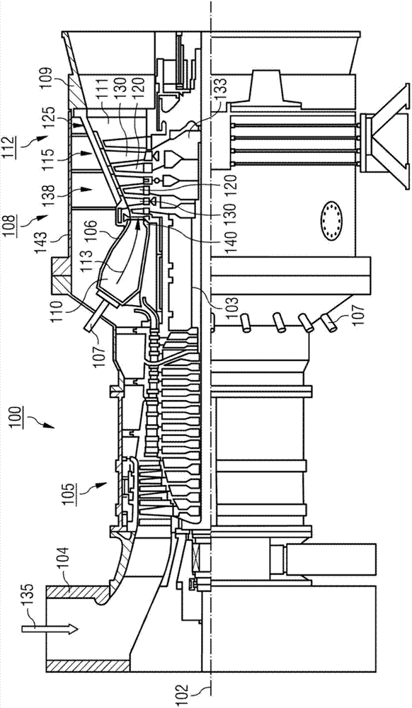
[0039] figure 1 Gas turbine 100 is shown by way of example in partial longitudinal section. Internally, the gas turbine 100 has a rotor 103 mounted in rotation about an axis of rotation 102 and a shaft 101 , which is also referred to as a turbine rotor.

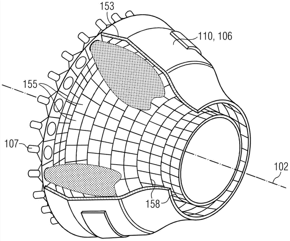
[0040] Arranged successively along the rotor 103 is an intake casing 104 , a compressor 105 , for example a torus-shaped combustion chamber 110 , especially an annular combustion chamber, and a plurality of coaxially arranged combustors 107 , turbines 108 and exhaust casings 109 .

[0041] The combustion chamber 110 is connected to, for example, an annular gas channel 111 . There, for example, four turbine stages 112 connected in series form the turbine 108 .

[0042] Each turbine stage 112 is formed, for example, from two blade rings. Seen along the flow direction of the working medium 113 , following the guide vane set 115 is a working vane set 125 composed of working vanes 120 .

[0043] Here, the guide vanes 130 are f...


PUM


Abstract

An injector (8) for introducing a fuel-air mixture into a combustion chamber: has a longitudinal axis (44) and includes a number of annular curved flow passages. Each flow passage comprises a fuel inlet opening (43), air inlet openings (42) and a fuel-air mixture outlet opening (9). The fuel inlet opening (43) is connected to a fuel distributor (41) and has a central axis (55) which runs perpendicular or parallel to the longitudinal axis (44) of the injector (8). The fuel-air mixture outlet opening (9) has a central axis which runs perpendicular to the longitudinal axis (44) of the injector (8). The air inlet openings (42) each have a central axis (54) which runs parallel to the longitudinal axis (44) of the injector (8).

Description

technical field [0001] The invention relates to an injector for introducing a fuel-air mixture into a combustion chamber, a combustion chamber and a gas turbine. Background technique [0002] Contemporary gas turbines should meet requirements regarding harmful emissions and environmental protection over a wider operating range. Meeting these requirements depends largely on the combustion system used in the gas turbine. In order to reduce the emission of nitrogen oxides (NOx), a low mixture ratio is used for premixing. In order to achieve high efficiency, a high turbine inlet temperature accompanied by a high flame temperature is then sought. Here, the already mentioned premixed flames are prone to thermoacoustic instabilities and NOx emissions due to high thermal power densities, which increase exponentially with flame temperature. [0003] Gas turbines, on the other hand, must operate at the lowest possible load and flame temperature in order to comply with power plant o...

Claims


Application Information

Patent Timeline
Patent Type & Authority Applications(China)
IPC IPC(8): F02C7/22F23R3/28
CPCF23R3/346F23R3/286
Inventor C.贝克O.黛丝W.克雷布斯B.维格纳
Owner SIEMENS AG
Learn More