
Hydraulic pipe cleaner and cleaning method thereof

A pipe dredger, hydraulic type technology, applied in indoor sanitary pipeline installations, water supply devices, buildings, etc., can solve the problems of insufficient suction, unsatisfactory dredging effect, and easy crushing of the pipe wall of the spring dredger, achieving Delicate dredging, small space occupation, fast dredging effect

Inactive Publication Date: 2014-12-17
NANJING COMM INST OF TECH +1
View PDF8 Cites 6 Cited by
  • Summary
  • Abstract
  • Description
  • Claims
  • Application Information

AI Technical Summary

Problems solved by technology

The suction of the spring type dredge is not enough, and the dredging effect is not ideal; the air pressure type needs to seal the mouth of the pipe, which is easy to crush the pipe wall; the electric wire type can be inserted into the pipe by stirring and winding to pick out the blockage, but for large bending Pipes, such as toilet sewers, cannot be used, and may damage the aging pipe wall, and the cost is not low

Method used


Image

  • Hydraulic pipe cleaner and cleaning method thereof
  • Hydraulic pipe cleaner and cleaning method thereof

Examples


Embodiment 1

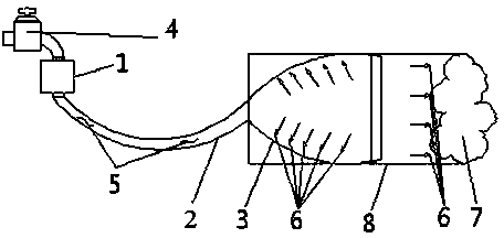
[0020] A hydraulic pipe dredger, comprising: an elastic rubber water guide pipe 2, a booster pump 1 is connected to one end of the elastic rubber water guide pipe 2, and a self-expanding nozzle 3 is connected to the other end of the elastic rubber water guide pipe 2. In this example,

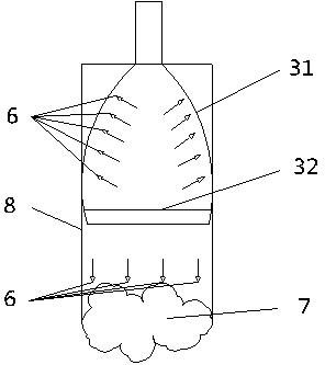
[0021] The self-expanding nozzle 3 is made up of a guide ring 31 and a horn-shaped bag 32, the large opening of the horn-shaped bag 32 is connected with the guide ring 31, and the small opening of the horn-shaped bag 32 is connected with the other end of the elastic rubber water guide pipe 2. One end is connected, and the shape of the trumpet-shaped capsule 32 presents a spherical crown.

Embodiment 2

[0023] A hydraulic pipeline dredging method, comprising the following steps:

[0024] Step 1 Take an elastic rubber tube as the elastic rubber aqueduct 2, connect the booster pump 1 and the self-expanding nozzle 3 at both ends of the elastic rubber aqueduct 2, and the self-expanding nozzle 3 is composed of a guide ring 31 and a trumpet-shaped bag 32, the large opening of the trumpet-shaped bag 32 is connected with the guide ring 31, and the small opening of the trumpet-shaped bag 32 is connected with the other end of the elastic rubber water guide pipe 2,

[0025] Step 2 Insert the self-expanding nozzle 3 into the pipeline to be dredged, the guide ring 31 in the self-expanding nozzle 3 forms a preliminary seal with the pipe wall of the pipeline to be dredged and slides on the pipeline to be dredged, driving the self-expanding nozzle 3 The trumpet-shaped bag 32 enters the pipeline to be dredged and falls into place. In this process, the guide ring 31 plays a guiding role, guidi...


PUM


Abstract

Provided are a hydraulic pipe cleaner and a cleaning method thereof. The pipe cleaner comprises an elastic rubber water diversion tube, one end of the elastic rubber water diversion tube is connected to a booster pump, and the other end of the elastic rubber water diversion tube is connected to a self-expanding nozzle. The method includes the steps of connecting the booster pump and the self-expanding nozzle to both ends of the elastic rubber water diversion tube respectively, wherein the self-expanding nozzle is composed of a guide ring and a horn-shaped bag, a large opening of the horn-shaped bag is connected to the guide ring, and a small opening of the horn-shaped bag is connected to the other end of the elastic rubber water diversion tube; inserting the self-expanding nozzle into a pipe to be cleaned, wherein the guide ring of the self-expanding nozzle forms preliminary sealing to the pipe wall of the pipe to be cleaned and slides in the pipe to be cleaned to drive the horn-shaped bag of the self-expanding nozzle to enter the pipe to be cleaned and settle down; starting the booster pump and filling water to the pipe to be cleaned to constantly increase the pressure of the cleaning water until clogging material in the pipe to be cleaned can be washed away by the high pressure cleaning water.

Description

technical field [0001] The invention relates to a hydraulic type pipeline dredging device and a dredging method thereof, which are suitable for dredging household pipelines. Background technique [0002] Pipe blockage is an inevitable problem that people will encounter in daily life. Therefore dredging pipeline is also the thing that every household must do, and the pipeline dredging device on the market is mostly spring type, air pressure type or electric wire type. The suction of the spring type dredge is not enough, and the dredging effect is not ideal; the air pressure type needs to seal the mouth of the pipe, which is easy to crush the pipe wall; the electric wire type can be inserted into the pipe by stirring and winding to pick out the blockage, but for the large bending range Pipes, such as toilet sewers, are unusable and may damage aging pipe walls, and the cost is not low. Therefore, pipeline dredging device also has room and necessity for improvement. Contents...

Claims


Application Information

Patent Timeline
Patent Type & Authority Applications(China)
IPC IPC(8): E03C1/306E03C1/308
Inventor 徐美娟张安梅国雄
Owner NANJING COMM INST OF TECH
Learn More