Auxiliary handle and reciprocating power tool having the same
A technology for assisting handles and working tools, applied in the field of reciprocating working tools, can solve problems such as the rotation limitation of the handle, and achieve the effects of improving performance and improving anti-vibration.
- Summary
- Abstract
- Description
- Claims
- Application Information
AI Technical Summary
Problems solved by technology
Method used
Image

Examples
no. 1 Embodiment approach
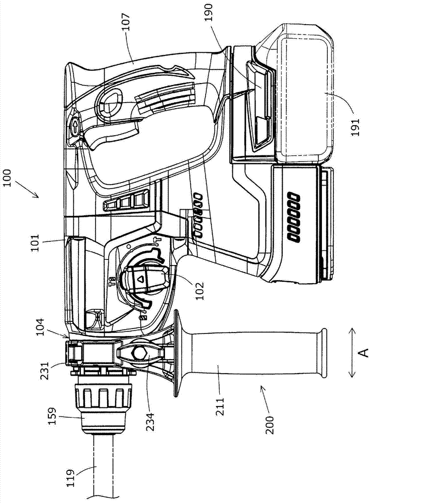
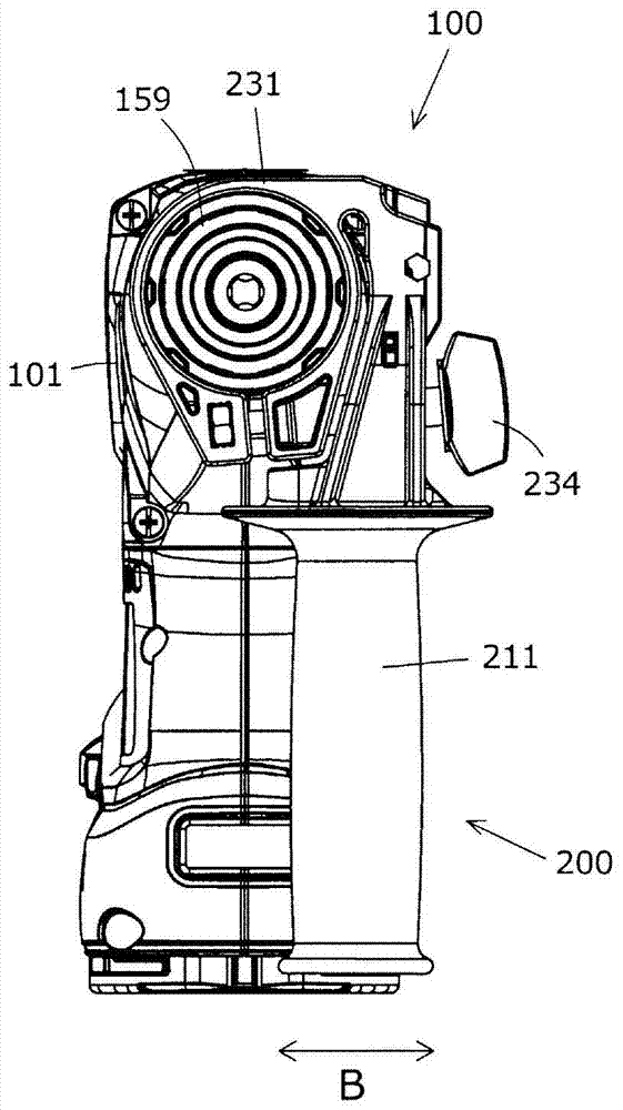
[0038] Below, refer to Figure 1 to Figure 5 Embodiments of the present invention will be described in detail. Such as figure 1 As shown, the auxiliary handle 200 is detachably attached to the hammer drill 100 . The hammer drill 100 is mainly composed of a main body 101 , a handle handle 107 , and a hammer head 119 .
[0039] Such as figure 1 As shown, the main body portion 101 has a tool holder 159 and a barrel portion 104 on its front side. The hammer head 119 is detachably attached to the tool holder 159 . On the other hand, a handle grip 107 is attached on the rear side opposite to the front side of the main body portion 101 . Also, a battery mounting portion 190 for mounting a battery pack 191 is provided below the handle handle 107 of the main body 101, and the battery pack 191 is detachable.
[0040] Inside the main body 101 are housed a motor, a power conversion mechanism that transmits the output force of the motor to the striker 119 , an impact mechanism, and a...
no. 2 Embodiment approach
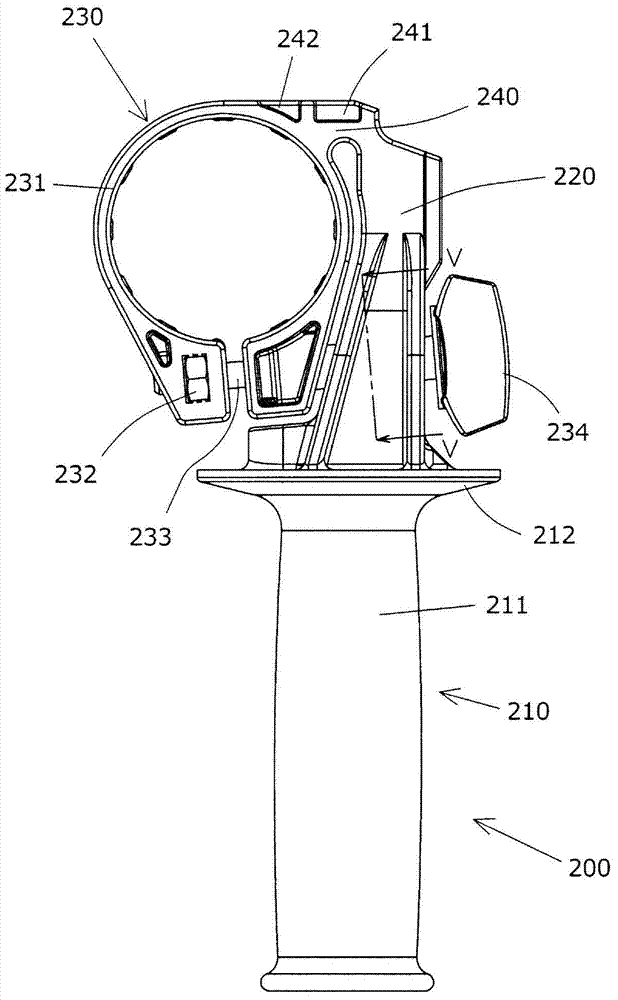
[0055] Below, refer to Image 6 A second embodiment will be described. Similar to the first embodiment, the auxiliary handle 300 is detachably attached to the cylindrical portion 104 of the hammer drill 100 . The auxiliary handle 300 is mainly composed of a handle portion 310 , a handle holding portion 320 , a mounting portion 330 , and a support portion 340 .
[0056] The handle portion 310 has an elongated handle 311 and a flange portion 312 provided on the handle holding portion 320 side. The handle part 310 is an embodiment corresponding to the "grip part" of the present invention.
[0057] The mounting portion 330 is mainly composed of an annular portion 331 . Nuts 332 and bolts 333 are provided on the annular portion 331 . A knob 334 is provided on the bolt 333 . The bolt 333 is tightened by turning the knob 334 , so that the mounting part 330 is mounted on the cylinder part 104 . This mounting part 330 is an embodiment corresponding to the "mounting part" of the p...
PUM
 Abstract
Description
Claims
Application Information
 - R&D
- Intellectual Property
- Life Sciences
- Materials
- Tech Scout
- Unparalleled Data Quality
- Higher Quality Content
- 60% Fewer Hallucinations
Browse by: Latest US Patents, China's latest patents, Technical Efficacy Thesaurus, Application Domain, Technology Topic, Popular Technical Reports.
© 2025 PatSnap. All rights reserved.Legal|Privacy policy|Modern Slavery Act Transparency Statement|Sitemap|About US| Contact US: help@patsnap.com