
Clamping-type three-phase voltage-source type inverter and control method thereof

A technology of three-phase voltage and control method, which is applied in the direction of electrical components, AC power input conversion to DC power output, output power conversion device, etc., which can solve the problems of unbalanced midpoint voltage, large current and power consumption of power electronic devices, Power electronic devices withstand problems such as excessive voltage, and achieve the effect of good output waveform quality and improvement of midpoint potential balance problems

Inactive Publication Date: 2014-12-10
SOUTHEAST UNIV
View PDF5 Cites 5 Cited by
  • Summary
  • Abstract
  • Description
  • Claims
  • Application Information

AI Technical Summary

Problems solved by technology

Assuming that this very high voltage change rate du / dt acts on the capacitive load, a current of du / dt is bound to be generated, which is called an inrush current. This current not only makes the power electronic device withstand a large instantaneous current and power dissipation, and can even cause damage to capacitive loads
[0004] Different from the two-level inverter, the inherent disadvantage in the diode-clamped three-level inverter is the problem of unbalanced midpoint voltage, and the capacitor on the DC bus has the function of filtering and supporting
Assuming that the midpoint potential changes greatly, it will cause the power electronic devices to withstand excessive voltage, so that it exceeds its tolerance range, causing damage to the power electronic devices

Method used


Image

  • Clamping-type three-phase voltage-source type inverter and control method thereof
  • Clamping-type three-phase voltage-source type inverter and control method thereof
  • Clamping-type three-phase voltage-source type inverter and control method thereof

Examples


Embodiment Construction

[0034] The present invention will be further described below in conjunction with the accompanying drawings.

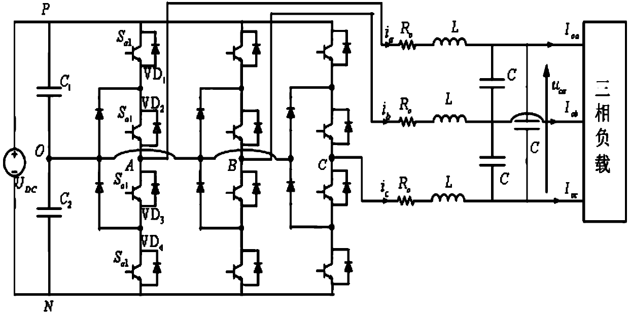
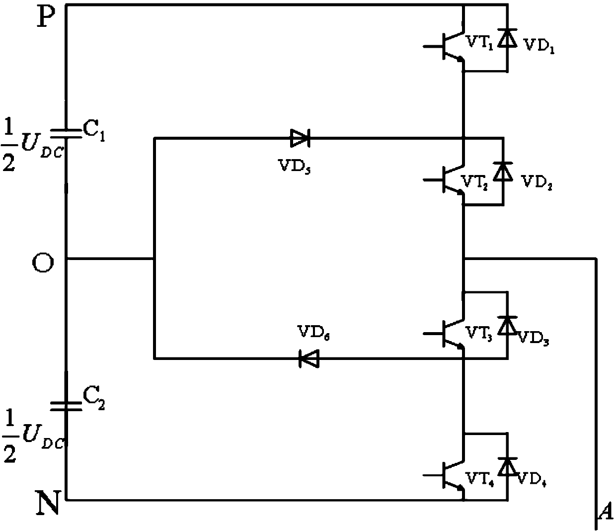
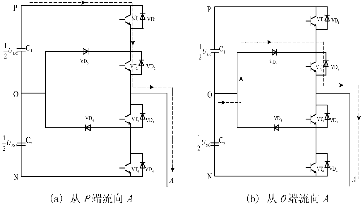
[0035] A three-level inverter based on a neutral point clamp, such as figure 1 As shown, including a DC power supply, a three-phase three-level inverter bridge, a three-phase LC filter and a three-phase load, the three-phase three-level inverter bridge includes three single-phase circuits connected in parallel and the first, The second capacitor; the first and second capacitors are C 1 , C 2 The first capacitor C 1 , DC power supply, second capacitor C 2 They are connected in series in sequence; in the figure, the filter inductance is L, the filter capacitor is C, and R o Represents the total effect of inductance loss, line impedance and switching tube turn-on and turn-off losses. The so-called three-level means that the output terminal of each phase on the AC side of the inverter obtains output voltages in three states from the intermediate DC circuit, which are ...


PUM


Abstract

The invention relates to a clamping-type three-phase voltage-source type inverter and a control method thereof and belongs to the technical field of three-phase voltage-source type inverters. The clamping-type three-phase voltage-source type inverter comprises a direct-current power source, a three-phase three-level inverter bridge, a three-phase LC filter and a three-phase load. In order to control output voltage waveforms, a mathematical model of the three-level inverter is established, an instantaneous value control system of the output voltage is put forward, a scheme combining a fundamental-wave disturbance instantaneous value controlled internal model with a harmonic disturbance repetitive controlled internal model under rotating coordinates is adopted, disturbance of the internal models is realized to acquire voltage output waveforms high in quality by adopting structural controllers in parallel, and a control method for fixing resultant vectors is adopted with an aim to solve problems about voltage jump of the three-level inverter and neutral voltage potential balance. The clamping-type three-phase voltage-source type inverter is ideal in comprehensive output voltage performance and good in output waveform quality, and meanwhile, the problems about voltage jump and neutral voltage potential balance are solved.

Description

technical field [0001] The invention relates to a clamped three-phase voltage source inverter and its control method, belonging to the technical field of three-phase voltage source inverters. Background technique [0002] In recent years, with the increasing demand for large-capacity power conversion devices in the industrial field, multi-level inverters have received more and more attention, and have begun to be widely researched and applied. Since the 20th century, multi-level inverters Since its development in the 1980s, several branches have appeared in the topological structure. The basic topology of multilevel inverters can be divided into three categories: diode-clamped multilevel inverters; leap capacitor multilevel inverters; and cascaded multilevel inverters. Three-level topology has been widely used in many fields such as medium and high voltage AC motor drive, reactive power compensation and absorption of power grid. Compared with the two-level structure, the m...

Claims


Application Information

Patent Timeline
Patent Type & Authority Applications(China)
IPC IPC(8): H02M7/487H02M7/5387
Inventor 余海涛孟高军胡敏强黄磊
Owner SOUTHEAST UNIV
Learn More