X ray and laser coaxial system

An X-ray and laser technology, applied in the field of X-ray radiation field measurement system, can solve the problems of difficult to realize the main axis of X-ray beam, unable to realize fast conversion, difficult to realize, etc., and achieve convenient coaxial processing of X-ray and laser. Effect

Inactive Publication Date: 2014-12-10
NAT INST OF METROLOGY CHINA
View PDF3 Cites 10 Cited by
  • Summary
  • Abstract
  • Description
  • Claims
  • Application Information

AI Technical Summary

Problems solved by technology

[0002] The X-ray standard radiation device is used in the verification, calibration and detection of X-ray radiation instruments, as well as in the fields of industrial non-destructive testing, but the existing equipment cannot realize the adjustment of the X-ray main beam axis direction, or the adjustment process is complicated and difficult to achieve The coaxiality of the main axis of the X-ray beam, the center of the beam-limiting diaphragm and the positioning device (positioning laser line) of the radiation instrument is difficult to achieve, especially when the positioning device is placed on a long guide rail with a variable stroke, so that it cannot be guaranteed The detector center of the inspection equipment is in the center of the X-ray beam, and it cannot be ensured that it is in the uniform radiation field; at the same time, most of the existing equipment is locked, and it is not suitable to disassemble after adjusting the beam and fixing the X-ray tube, and it is difficult to reset , and this method is difficult to reset after the position is changed due to vibration, collision and other reasons during use; at the same time, the filtering adjustment of the X-ray beam radiation quality in the prior art usually adopts a manual switching method. Faster conversion cannot be achieved. Moreover, most laboratories have an X-ray tube equipped with an additional filter turntable. When using more radiation beam specifications, it is necessary to disassemble the filter turntable and other operations, which is very inconvenient. Some solutions That is to configure more X-ray machines, so that the laboratory space, control equipment and other existing equipment are not fully utilized

Method used


Image

  • X ray and laser coaxial system
  • X ray and laser coaxial system
  • X ray and laser coaxial system

Examples


Embodiment Construction

[0043] The technical solutions of the present invention will be described in further detail below with reference to the accompanying drawings and embodiments.

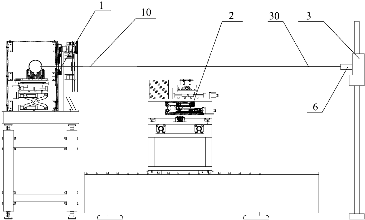
[0044] figure 1 It is a schematic diagram of the X-ray and laser coaxial system of the present invention, as shown in the figure, the present invention includes an ionization chamber adjustment device 2 and a laser adjustment device 3 .

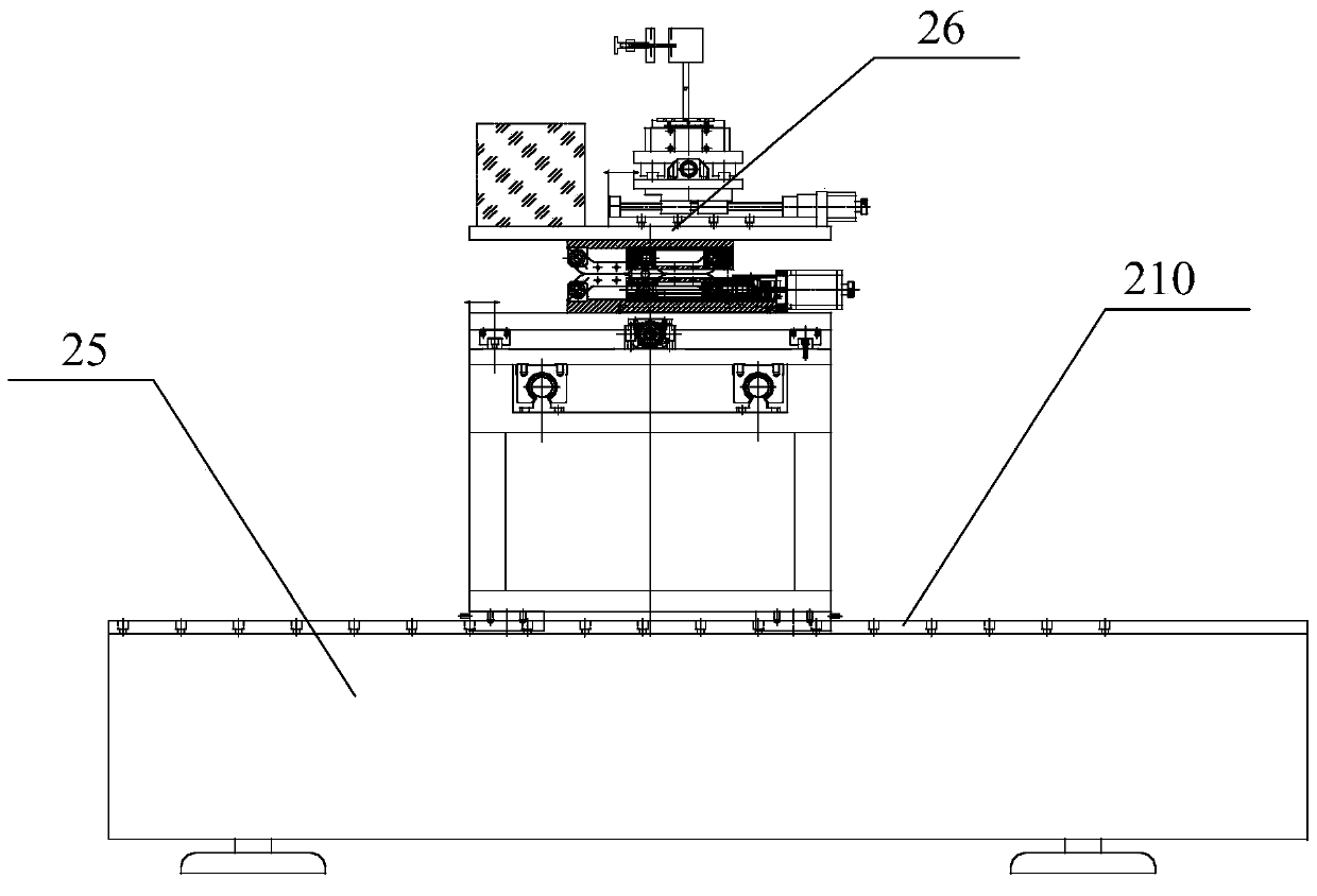
[0045] The ionization chamber adjustment device 2 has a first guide rail 210 for setting up an ionization chamber or an area array flat panel detector. The ionization chamber or area array flat panel detector receives the X-rays 10 emitted from one side of the ionization chamber adjustment device. The first rail 210 It is parallel to the X-ray 10, and the beam center of the X-ray 10 coincides with the center of the area array flat panel detector. Specifically, the X-ray 10 may be emitted from the X-ray tube 9 of the X-ray emitting device 1 .

[0046] The laser adjustment device 3 is...


PUM


Abstract

The invention relates to an X ray and laser coaxial system. The X ray and laser coaxial system comprises an ionization chamber adjusting device and a laser adjusting device; the ionization chamber adjusting device comprises a first track which is parallel to an X ray; the beam center of the X ray and the center of an array flat-panel detector are overlapped; the laser adjusting device is located at a corresponding position of one side of the ionization chamber adjusting device; a laser which is used for emitting a laser is clamped by the laser adjusting device; when the laser irradiates on the array flat-panel detector, the laser emergent position of the laser is adjusted to enable the cross center of the laser and the center of the array flat-panel detector to be overlapped; the relative distance of the array flat-panel detector and the laser adjusting device is changed and the laser emergent position of the laser is adjusted again to enable the cross center of the laser and the center of the array flat-panel detector to be overlapped again; the laser emergent position of the laser is adjusted to until the cross center of the laser and the center of the array flat-panel detector to be always overlapped so as to enable the laser and the X ray to be coaxial. According to the X ray and laser coaxial system, the coaxial treatment on the X ray and the laser is convenient to achieve.

Description

technical field [0001] The invention relates to an X-ray and laser coaxial system, in particular to a measurement system for X-ray radiation field. Background technique [0002] The X-ray standard radiation device is used in the verification, calibration and detection of X-ray radiation instruments, as well as in the fields of industrial non-destructive testing, but the existing equipment cannot realize the adjustment of the X-ray main beam axis direction, or the adjustment process is complicated and difficult to achieve The coaxiality of the main axis of the X-ray beam, the center of the beam-limiting diaphragm and the positioning device (positioning laser line) of the radiation instrument is difficult to achieve, especially when the positioning device is placed on a long guide rail with a variable stroke, so that it cannot be guaranteed The detector center of the inspection equipment is in the center of the X-ray beam, and it cannot be ensured that it is in the uniform rad...

Claims


Application Information

Patent Timeline
IPC IPC(8): G01T7/00G01C15/00
Inventor 吴金杰陈法君蒋伟李兵郭彬
Owner NAT INST OF METROLOGY CHINA
Why Eureka
Try Eureka