
Protecting device for flue gas ducts of electric arc furnace

A protection device, electric arc furnace technology, applied in the field of electric arc furnace flue gas flue, can solve the problems of consuming industrial water, wasting heat, affecting the safe production of electric furnaces, etc., achieving small thermal conductivity, reducing heat loss of flue gas, and improving waste heat recovery. amount of effect

Inactive Publication Date: 2014-12-10
孙慕文
View PDF7 Cites 1 Cited by
  • Summary
  • Abstract
  • Description
  • Claims
  • Application Information

AI Technical Summary

Problems solved by technology

In the production process of the electric arc furnace, water leakage accidents often occur in the water-cooled flue of the furnace cover, the mobile water-cooled flue, and the fixed water-cooled flue, which not only affects the normal operation of the electric furnace flue gas waste heat recovery system, but also seriously affects the safe production of the electric furnace
In addition, the water-cooled flue of the furnace cover, the mobile water-cooled flue and the fixed flue are all cooled by industrial water, which not only consumes a lot of industrial water, but also wastes a lot of recoverable heat.

Method used


Image

  • Protecting device for flue gas ducts of electric arc furnace
  • Protecting device for flue gas ducts of electric arc furnace
  • Protecting device for flue gas ducts of electric arc furnace

Examples


Embodiment 1

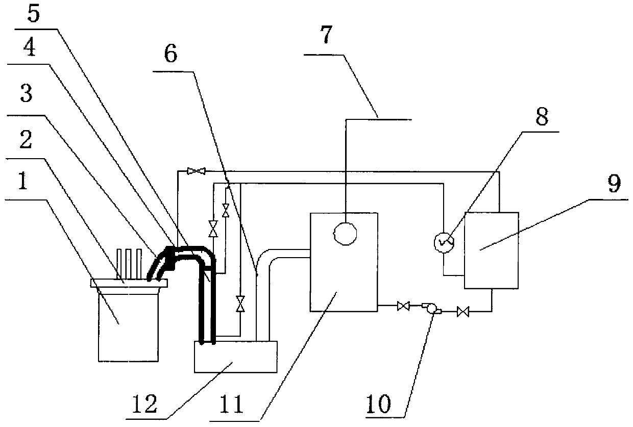
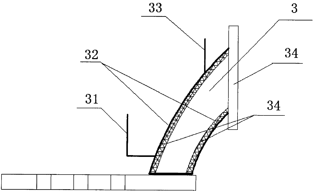
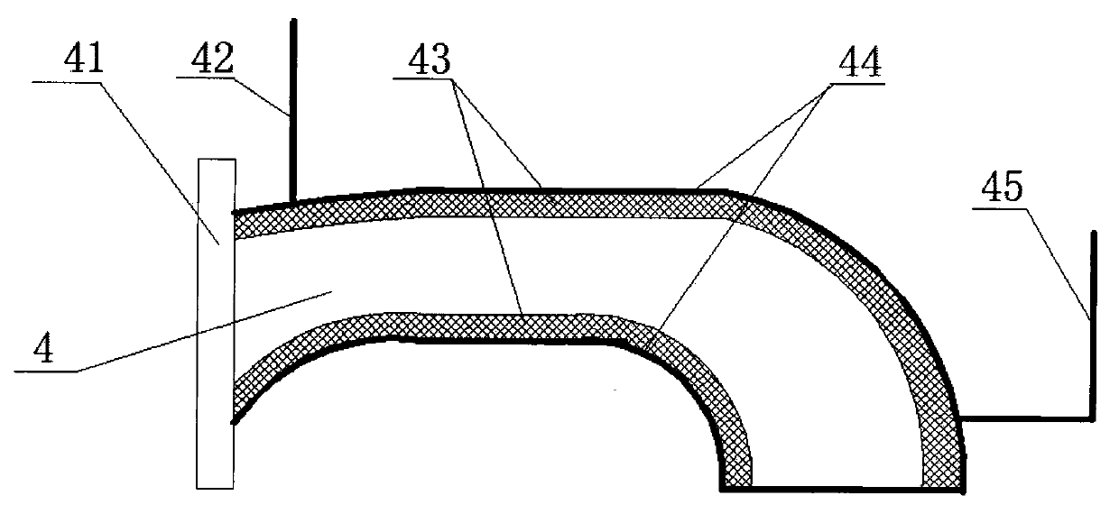
[0026] Such as figure 1 Shown: a protection device for the flue gas flue of an electric arc furnace, including the furnace cover (2) of the electric arc furnace (1), the water-cooled flue (3) of the electric arc furnace cover, the mobile water-cooled flue (4), and the fixed flue (5) and combustion settling chamber (10). Such as figure 2 , image 3 , Figure 4 Shown: Stainless steel nails are installed on the inside of the water-cooled flue (3), the mobile water-cooled flue (4) and the fixed flue (5) of the furnace cover, that is, on the wall of the water-cooled steel pipe on the side contacting the high-temperature flue gas. Install the stainless steel bars on the nails, and then pour the brown corundum castable. The thickness of the castable is controlled at 5-8mm. After pouring is completed, dry naturally for one week, and then use forced drying for one week according to the requirements of castables. The temperature rise of the flue gas in forced drying should not exce...

Embodiment 2

[0029] Such as figure 1 Shown: a protection device for the flue gas flue of an electric arc furnace, including the furnace cover (2) of the electric arc furnace (1), the water-cooled flue (3) of the electric arc furnace cover, the mobile water-cooled flue (4), and the fixed flue (5) and combustion settling chamber (10). Such as figure 2 , image 3 , Figure 4 Shown: Stainless steel nails are installed on the inside of the water-cooled flue (3), the mobile water-cooled flue (4) and the fixed flue (5) of the furnace cover, that is, on the wall of the water-cooled steel pipe on the side contacting the high-temperature flue gas. Install stainless steel bars on the nails, and then pour mullite castables. The thickness of the castables is controlled at 8-10 mm. After pouring is completed, dry naturally for one week, and then use forced drying for one week according to the requirements of castables. The temperature rise of the flue gas in forced drying should not exceed 5°C / hour...


PUM


Abstract

The invention discloses a protecting device for flue gas ducts of an electric arc furnace. The protecting device comprises a furnace lid of the electric arc furnace, a furnace lid water-cooling gas duct, a moving water-cooling gas duct, a fixed gas duct, a burning settling chamber and the like, wherein high temperature-resistant abrasion-resistant casting materials are poured on the inner sides of the furnace lid water-cooling gas duct of the electric arc furnace, the moving water-cooling gas duct and the fixed gas duct entering the burning settling chamber. The protecting device can greatly prolong service lives of the furnace lid water-cooling gas duct, the moving water-cooling gas duct and the fixed gas duct, and the service lives are prolonged to 1.5 years or above from 3 months in average at present.

Description

technical field [0001] The invention relates to an electric arc furnace flue gas flue, in particular it can greatly extend the life of the electric arc furnace flue gas flue, greatly reduce the heat of the flue gas taken away by cooling water, and increase the heat recovered by the electric furnace flue gas waste heat system , belongs to the technical field of electric arc furnace safety production and energy saving. Background technique [0002] At present, in the production process of electric arc furnace steelmaking, the temperature of the flue gas discharged from the furnace cover flue is very high, generally at 1300 ° C ~ 1600 ° C, the flue gas flow rate is 50 ~ 100 m / s, and the dust content is 2 ~ 30 g / m 3 , Under the action of such high temperature, high speed and high dusty flue gas, the average life of the water-cooled flue, mobile water-cooled flue and fixed flue of the furnace cover is 2 to 3 months. During the production process of the electric arc furnace, wat...

Claims


Application Information

Patent Timeline
Patent Type & Authority Applications(China)
IPC IPC(8): F27B3/14F27B3/24
Inventor 孙慕文
Owner 孙慕文
Learn More