A cabin integrated electro-hydraulic servo mechanism
What is Al technical title?
Al technical title is built by PatSnap Al team. It summarizes the technical point description of the patent document.
An electro-hydraulic servo and electro-hydraulic servo valve technology, applied in servo motors, servo motor components, mechanical equipment, etc., can solve the problems of inability to meet the requirements of use, high processing accuracy requirements, sensitive to oil pollution, etc., to achieve easy installation and The effect of post-maintenance, ensuring reliability and reducing energy consumption
Active Publication Date: 2016-04-13
HUBEI SANJIANG AEROSPACE HONGFENG CONTROL
View PDF6 Cites 0 Cited by
Summary
Abstract
Description
Claims
Application Information
AI Technical Summary
This helps you quickly interpret patents by identifying the three key elements:
Problems solved by technology
Method used
Benefits of technology
Problems solved by technology
However, due to the low stiffness, it cannot meet the requirements in some military applications; the electro-hydraulic servo mechanism uses hydraulic oil as the working medium, and the flow and direction of the output oil are changed through the electro-hydraulic servo valve to provide power transmission.
It has the advantages of high load rigidity, wide system frequency band, and fast response. At the same time, it also has problems such as high processing accuracy, sensitivity to oil pollution, and easy oil leakage.
With the development of electro-hydraulic servo technology, new technologies and methods are generally adopted to gradually improve the shortcomings of electro-hydraulic servo mechanisms, but the problems of large volume and low integration still exist
Method used
Image
Click on the blue label to locate the original text in one second.
Reading with bidirectional positioning of images and text.
Examples
Embodiment Construction
[0030] In order to make the object, technical solution and advantages of the present invention clearer, the present invention will be further described in detail below in conjunction with the accompanying drawings and embodiments. It should be understood that the specific embodiments described here are only used to explain the present invention, not to limit the present invention.
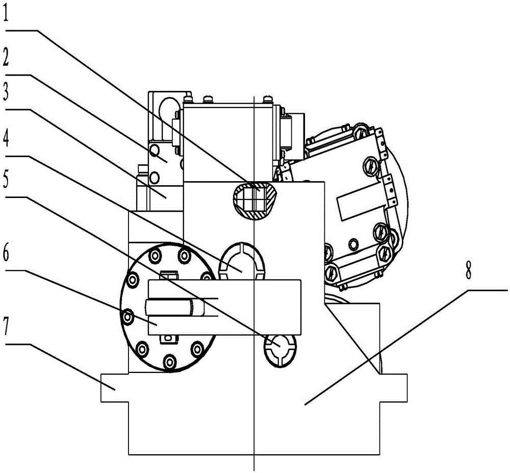
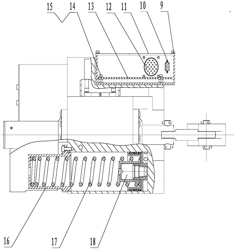
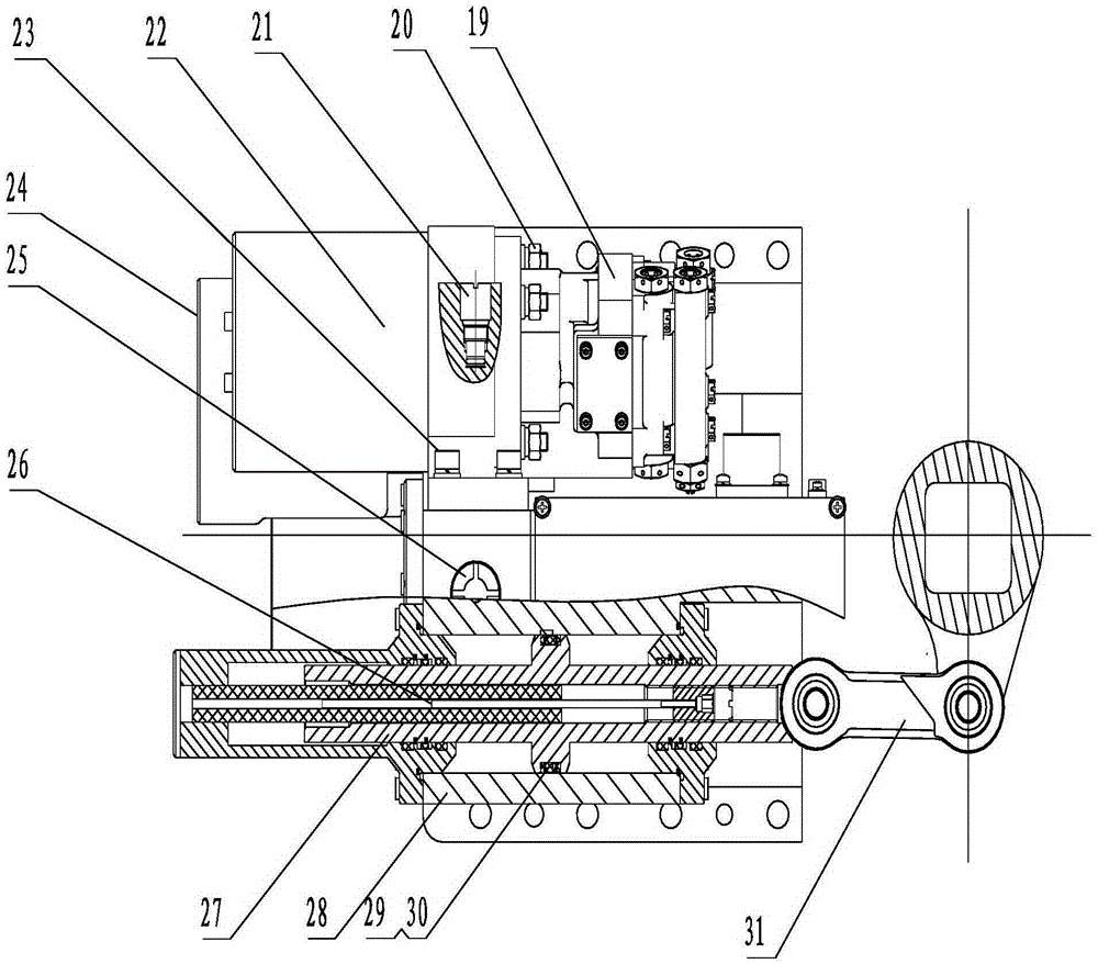
[0031] figure 1 , figure 2 and image 3 It is a structural schematic diagram of the cabin-integrated electro-hydraulic servo mechanism according to the present invention. It mainly includes motor pump combination, hydraulic components, mechanical transmission mechanism, control mechanism and other four parts, which are integrated and installed on the body 7. At the same time, the output shaft of the mechanism is integrated with the rudder shaft connected to the cabin, adopting an integrated design , so the overall device has the advantages of compact structure, small volume, light weight, and e...
PUM
Abstract
The invention discloses an integrated electro-hydraulic servo mechanism for a cabin. The servo mechanism is composed of a body, a motor pump combination, a hydraulic assembly, a mechanical transmission mechanism and a control mechanism, wherein the motor pump combination, the hydraulic assembly, the mechanical transmission mechanism and the control mechanism are integrally installed on the body. After being powered on, a motor drives a constant-pressure variable pump to rotate so as to enable electric energy to be converted into hydraulic energy; the hydraulic assembly is mainly composed of an oil tank, a pressurization component, a check valve, a high-pressure safety valve, a low-pressure safety valve, a filing valve, a high-pressure oil filter, a low-pressure oil filter, a hydraulic cylinder, an energy accumulator, an electro-hydraulic servo valve and the like; the mechanical transmission mechanism comprises a piston connecting rod, an actuating cylinder, a rocker, a connecting rod mechanism, a locking mechanism and the like; the control mechanism comprises a plug, a socket, a linear displacement sensor used for detecting the position of a piston rod in the actuating cylinder and a control circuit board for achieving closed loop of a system. The servo mechanism has the advantages of being high in power-to-volume ratio and power-to-weight ratio, rapid in response, high in rigidity, high in control accuracy and the like.
Description
technical field [0001] The invention belongs to the field of electromechanical equipment, and in particular relates to a cabin-integrated electro-hydraulic servo mechanism. Background technique [0002] Servo mechanisms are widely used in machinery manufacturing and military fields, and are generally used to provide power output. At present, the common servo mechanisms mainly include three categories: pneumatic servo mechanisms, electric servo mechanisms, and electro-hydraulic servo mechanisms. They each have the following characteristics: [0003] Pneumatic servos are powered by compressed air, which transfers energy to the actuator, thereby providing power delivery. Its structure is relatively simple, its cost is low, and its anti-pollution ability is strong. However, due to the compressibility of gas, the output torque of the system is small, its dynamic response is slow, and its stiffness is low. The electric servomechanism uses electric power as energy, and transmits...
Claims
Application Information
Patent Timeline
Application Date:The date an application was filed.
Publication Date:The date a patent or application was officially published.
First Publication Date:The earliest publication date of a patent with the same application number.
Issue Date:Publication date of the patent grant document.
PCT Entry Date:The Entry date of PCT National Phase.
Estimated Expiry Date:The statutory expiry date of a patent right according to the Patent Law, and it is the longest term of protection that the patent right can achieve without the termination of the patent right due to other reasons(Term extension factor has been taken into account ).
Invalid Date:Actual expiry date is based on effective date or publication date of legal transaction data of invalid patent.