
A method of manufacturing a semiconductor device

A manufacturing method and semiconductor technology, applied in the direction of semiconductor devices, electrical components, circuits, etc., can solve the problems of loss, reduction of equivalent oxide layer thickness, influence of device negative bias temperature instability, etc., to improve performance, improve Negative bias temperature instability, the effect of ensuring the equivalent thickness of the oxide layer

Active Publication Date: 2017-09-01
SEMICON MFG INT (SHANGHAI) CORP
View PDF6 Cites 0 Cited by
  • Summary
  • Abstract
  • Description
  • Claims
  • Application Information

AI Technical Summary

Problems solved by technology

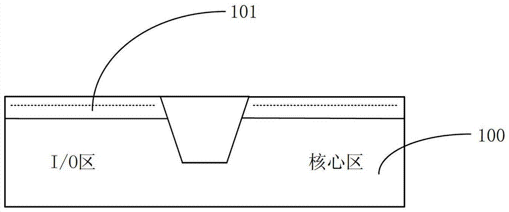
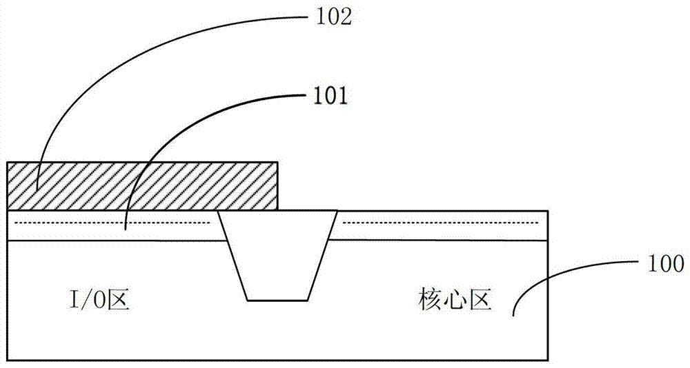
[0019] In the above-mentioned manufacturing method of the semiconductor device, in the process of stripping and removing the patterned photoresist 102, a part of the I / O region interface layer 101 located under the patterned photoresist 102 is usually removed, resulting in The damage and thickness loss of the silicon oxynitride layer in the interface layer 101 in the I / O area will cause the equivalent oxide thickness (EOT) of the interface layer 101 in the I / O area to decrease, which will affect the performance of devices in the I / O area.
Moreover, damage to the interface layer 101 in the I / O region will affect the negative bias temperature instability (Negative Bias Temperature Instability) of the device, which will also cause performance degradation of the semiconductor device

Method used


Image

  • A method of manufacturing a semiconductor device
  • A method of manufacturing a semiconductor device
  • A method of manufacturing a semiconductor device

Examples


Embodiment Construction

[0043] In the following description, numerous specific details are given in order to provide a more thorough understanding of the present invention. It will be apparent, however, to one skilled in the art that the present invention may be practiced without one or more of these details. In other examples, some technical features known in the art are not described in order to avoid confusion with the present invention.

[0044] In order to thoroughly understand the present invention, detailed steps will be presented in the following description in order to explain the manufacturing method of the semiconductor device proposed by the present invention. Obviously, the practice of the invention is not limited to specific details familiar to those skilled in the semiconductor arts. Preferred embodiments of the present invention are described in detail below, however, the present invention may have other embodiments besides these detailed descriptions.

[0045] It should be understo...


PUM


Abstract

The invention provides a semiconductor device manufacturing method, and relates to the technical field of semiconductors. The method comprises steps: S101, a semiconductor substrate with an I / O region and a core region is provided, and an I / O region interface layer covering the I / O region and the core region is formed on the semiconductor substrate; S102, nitriding and annealing after nitriding are carried out on the I / O region interface layer; S103, oxidizing is carried out on the I / O region interface layer; S104, a patterned photoresist is formed above the part, located in the I / O region, of the I / O region interface layer; S105, the patterned photoresist serves as a mask to etch and remove the part, located in the core region, of the I / O region interface layer; and S106, the patterned photoresist is removed. Through adding the step of annealing after nitriding and the step of oxidizing in the existing process, the thickness of the equivalent oxide layer of the I / O region interface layer can be ensured, negative bias temperature instability of the device can be improved, and the performance of the semiconductor device can be improved.

Description

technical field [0001] The invention relates to the technical field of semiconductors, in particular to a method for manufacturing a semiconductor device. Background technique [0002] In the field of semiconductor technology, as the size of devices continues to shrink, high-k metal gate technology has become a technology with broad application prospects. In high-k metal gate technology, silicon dioxide doped with nitrogen on top is generally used as the interfacial layer (IL) of the gate. [0003] When the process node of semiconductor technology develops to 32nm and below, in semiconductor devices using high-k metal gate technology, the thickness of the interface layer will be further reduced (compared to the previous process node greater than 32nm). In the prior art, silicon dioxide doped with nitrogen at the top is generally used as the interface layer (that is, the interface layer includes a silicon dioxide layer and a silicon oxynitride layer located above it). In se...

Claims


Application Information

Patent Timeline
Patent Type & Authority Patents(China)
IPC IPC(8): H01L21/28
CPCH01L29/42364
Inventor 禹国宾
Owner SEMICON MFG INT (SHANGHAI) CORP
Learn More