
High-pressure gas oil injection device

An oil injection device and high-pressure gas technology, applied in the field of aerated concrete block production equipment, can solve the problems of increased oil consumption, blockage of oil injection holes, insufficient uniformity of oil injection, etc., and achieve the effect of reducing the probability of blockage

Inactive Publication Date: 2014-12-03
合肥大来新型建材有限公司
View PDF6 Cites 3 Cited by
  • Summary
  • Abstract
  • Description
  • Claims
  • Application Information

AI Technical Summary

Problems solved by technology

The working principle of the existing oil injection equipment is mainly to directly pressurize the oil and spray it out. In order to reduce the production cost of the aerated concrete block, the oil usually used is waste engine oil. Since the waste engine oil contains more impurities, the above-mentioned Oil injection equipment often has clogged oil injection holes, and the uniformity of the above-mentioned oil injection equipment is insufficient, which is not conducive to the uniform distribution of oil and increases the amount of oil used

Method used


Image

  • High-pressure gas oil injection device
  • High-pressure gas oil injection device
  • High-pressure gas oil injection device

Examples


Embodiment Construction

[0013] The content of the present invention will be described below in conjunction with specific embodiments.

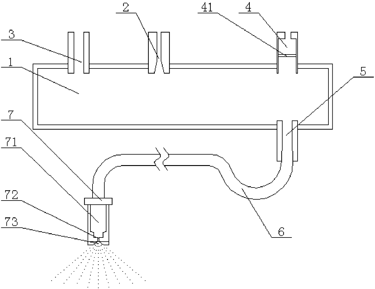
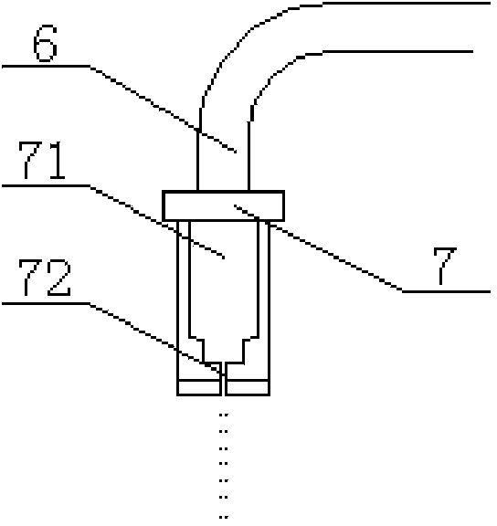
[0014] Such as Figure 1 to Figure 3 As shown, it is a structural schematic diagram of a high-pressure gas fuel injection device according to the present invention. A high-pressure gas fuel injection device according to the present invention includes: a mixing cylinder 1, an air inlet 3 is provided on the top wall of one end of the mixing cylinder 1, and an air outlet 4 is provided on the top wall of the other end of the mixing cylinder 1, so that The air outlet 4 is provided with an oil-repellent gas-permeable film 41, and the top wall of the mixing cylinder 1 is also provided with an oil inlet 2, and the oil inlet 2 is located between the air inlet 3 and the air outlet 4 , the bottom of the mixing cylinder 1 is provided with an oil outlet 5, and the oil outlet 5 and the air outlet 4 are located at the same end of the mixing cylinder 1; the connecting hose 6 and th...


PUM


Abstract

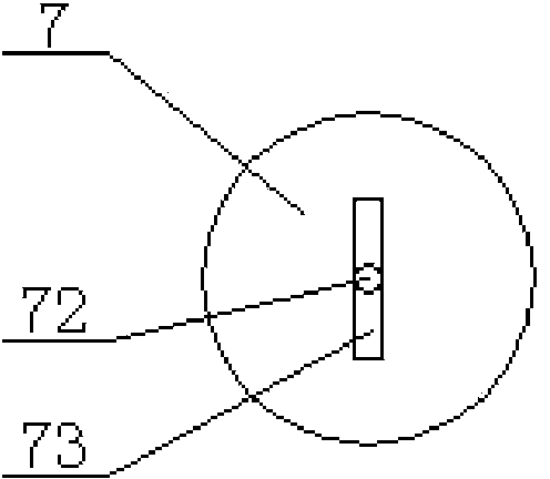
The invention discloses a high-pressure gas oil injection device. The high-pressure gas oil injection device comprises a mixing cylinder, a connecting hose and a nozzle, wherein a gas inlet is formed in the top wall at one end of the mixing cylinder; a gas outlet is formed in the top wall at the other end of the mixing cylinder; an oil-resistant breathable film is arranged in the gas outlet; an oil inlet is further formed in the top wall of the mixing cylinder, and is positioned between the gas inlet and the gas outlet; an oil outlet is formed in the bottom of the mixing cylinder; the oil outlet and the gas outlet are positioned at the same end of mixing cylinder; one end of the connecting hose is connected with the oil outlet, and the other end of the connecting hose is connected with the nozzle; a connecting cavity, an atomizing injecting opening and a fan-shaped injecting groove are formed in the nozzle; one end of the connecting cavity is connected with the connecting hose, and the other end of the connecting cavity is connected with the atomizing injecting opening; the fan-shaped injecting groove is formed in the spraying end of the nozzle; the atomizing injecting opening is positioned in the fan-shaped injecting groove.

Description

technical field [0001] The invention relates to a high-pressure gas injection device, which belongs to the technical field of aerated concrete block production equipment. Background technique [0002] In the production process of aerated concrete blocks, the mold is required to be poured after the raw materials are fully mixed, and the repeatedly used mold needs to be cleaned and sprayed before each pouring operation. The working principle of the existing oil injection equipment is mainly to directly pressurize the oil and spray it out. In order to reduce the production cost of the aerated concrete block, the oil usually used is waste engine oil. Since the waste engine oil contains more impurities, the above-mentioned The oil injection equipment often has the situation that the oil injection hole is blocked, and the uniformity of the oil injection of the above-mentioned oil injection equipment is insufficient, which is not conducive to the uniform distribution of oil and inc...

Claims


Application Information

Patent Timeline
Patent Type & Authority Applications(China)
IPC IPC(8): B28B7/38
CPCB28B7/38
Inventor 周勇李新华
Owner 合肥大来新型建材有限公司
Learn More