
Improved biconical antenna for UHF waveband passive radar

A technology of external radiation source radar and biconical antenna, which is applied in the field of passive positioning, external radiation source radar and antenna, and wireless communication. problem, to achieve the effect of light weight, guaranteed reception performance, and small size

Inactive Publication Date: 2014-11-26
WUHAN UNIV
View PDF2 Cites 5 Cited by
  • Summary
  • Abstract
  • Description
  • Claims
  • Application Information

AI Technical Summary

Problems solved by technology

The biconical antenna is a typical broadband omnidirectional antenna, but for the traditional biconical antenna, the voltage standing wave ratio (Voltage Standing Wave Ratio, VSWR) and the main-side lobe ratio cannot simultaneously achieve ideal indicators
If you want to get a smaller VSWR, you need to use a longer conical vibrator as the radiation arm of the antenna to reduce the energy reflection at the end of the antenna, but the long biconical antenna will cause narrowing of the beam width and the generation of side lobes, and at the same time It will also cause the volume of the antenna to be too large; on the other hand, if you want to weaken or even eliminate the side lobe of the antenna lobe pattern, you need to use a shorter conical dipole as the radiation arm of the antenna, but the end reflection of the short biconical antenna Strong, so the VSWR is too large
[0005]In addition, in order to improve the maneuverability of the external radiation source radar, the volume of the antenna should not be too large, and the traditional biconical antenna generally uses a conical vibrator with a large cone angle as the The radiation arm is too bulky and inconvenient for application

Method used

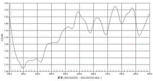
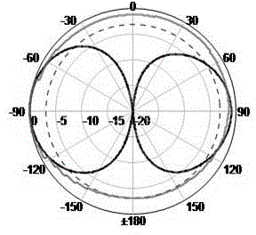

Image

  • Improved biconical antenna for UHF waveband passive radar
  • Improved biconical antenna for UHF waveband passive radar
  • Improved biconical antenna for UHF waveband passive radar

Examples


Embodiment Construction

[0024] In order to facilitate those of ordinary skill in the art to understand and implement the present invention, the present invention will be described in further detail below in conjunction with the accompanying drawings and embodiments. It should be understood that the implementation examples described here are only used to illustrate and explain the present invention, and are not intended to limit this invention.

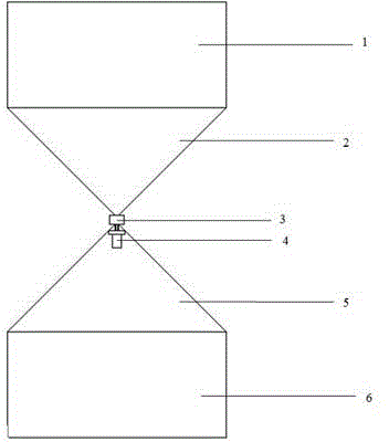
[0025] please see figure 1 , the technical solution adopted in the present invention is: a UHF-band external radiation source radar improved biconical antenna, including an upper radiation arm, a lower radiation arm and a feeding structure, and the upper radiation arm and the lower radiation arm are mutually symmetrical and coaxially connected. integrated; the first cylindrical vibrator 1 and the first conical vibrator 2 are connected together to form the upper radiating arm, and the second conical vibrator 5 and the second cylindrical vibrator 6 are connect...


PUM


Abstract

The invention discloses an improved biconical antenna for UHF waveband passive radar. The antenna comprises an upper radiation arm, a lower radiation arm and a feed structure, wherein the upper radiation arm and the lower radiation arm are symmetrically and coaxially arranged and connected into a whole, a first cylindrical vibrator and a first conical vibrator are connected to form the upper radiation arm, a second conical vibrator and a second cylindrical vibrator are connected to form the lower radiation arm, the diameter of the top surface of each conical vibrator is equal to the diameter of each cylindrical vibrator, the first conical vibrator and the second conical vibrator are symmetrically arranged in the mode that conical tips are opposite, and the first conical vibrator and the second conical vibrator are not in contact; the feed structure is composed of an SMA-K type connector and a 1:1 balun, the SMA-K type connector is arranged on the internal conical tip portion of the second conical vibrator, the balun is arranged between the first conical vibrator and the second conical vibrator, the SMA-K type connector is connected with the input end of the balun, and the output end of the balun is connected with the upper radiation arm and the lower radiation arm of the biconical antenna. According to the improved biconical antenna, directional diagram consistency is higher on the working band, the size is smaller, and the antenna is convenient to carry.

Description

[0001] technical field [0002] The invention belongs to the technical field of wireless communication, passive positioning, external radiation source radar and antenna, and relates to an improved biconical antenna for UHF band external radiation source radar. [0003] Background technique [0004] External radiation source radar is a bistatic / multistatic radar system that uses electromagnetic signals emitted by a third party to detect target characteristics. Radar with radiation sources outside the UHF band mainly uses wireless TV signals in the 470-806MHz frequency band, and its receiving antenna should first have broadband characteristics. At the same time, in order to meet the needs of all-round target monitoring for radars with external radiation sources in the UHF band, the receiving antenna is required to be omnidirectional in the azimuth plane and have a wide half-power beamwidth in the elevation plane. The biconical antenna is a typical broadband omnidirectional a...

Claims


Application Information

Patent Timeline
Patent Type & Authority Applications(China)
IPC IPC(8): H01Q1/36H01Q1/50
Inventor 龚子平曹小毛万显荣柯亨玉
Owner WUHAN UNIV
Learn More