Electrolyte vacuum stirring bubble-removal device with self-cleaning function

A technology of vacuum stirring and automatic cleaning, which is used in the manufacture of electrical components, non-aqueous electrolyte batteries, and electrolyte batteries, etc. It can solve the problems of unstable injection accuracy, poor equipment injection process, and unsatisfactory treatment effect.

Active Publication Date: 2014-11-26
DONGGUAN HONBRO LI BATTERY EQUIP TECH
View PDF6 Cites 5 Cited by
  • Summary
  • Abstract
  • Description
  • Claims
  • Application Information

AI Technical Summary

Problems solved by technology

[0003] In the existing battery production process, more air bubbles are generated in the liquid injection pipeline, that is, there will be more air bubbles in the electrolyte, which often leads to dripping and unstable injection accuracy during liquid injection. However, there are more air bubbles in the injected electrolyte, which affects the battery capacity and cycle life, and also reduces the product quality.
[0004] In addition, liquid injection devices and liquid storage tanks are prone to crystallization and solidification after a long period of time, resulting in pipeline blockage and affecting the subsequent liquid injection process. The solidification of liquid crystals is more prone to clogging. For example, after a period of holidays in the factory, it is often found that the equipment cannot perform the liquid injection process well when the factory restarts. At this time, manual cleaning is also troublesome, time-consuming, and the treatment effect is not good. ideal

Method used


Image

  • Electrolyte vacuum stirring bubble-removal device with self-cleaning function
  • Electrolyte vacuum stirring bubble-removal device with self-cleaning function
  • Electrolyte vacuum stirring bubble-removal device with self-cleaning function

Examples


Embodiment Construction

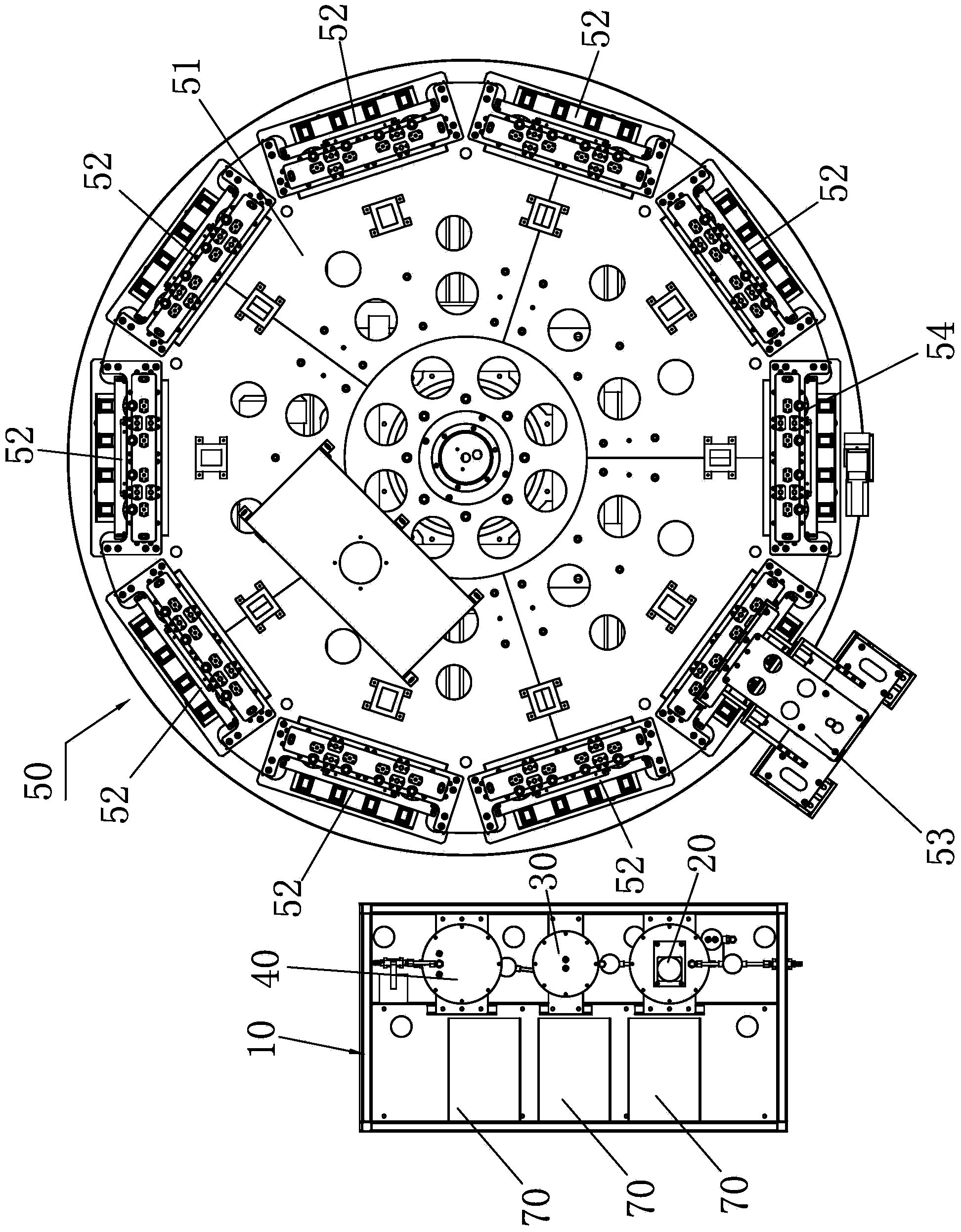
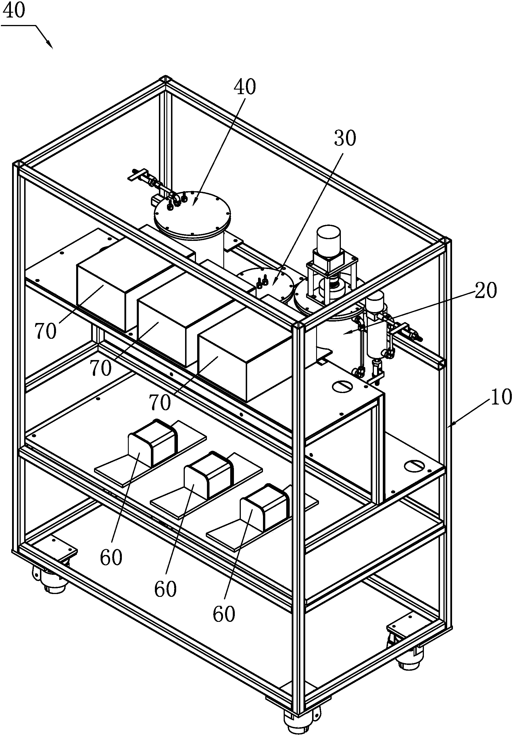
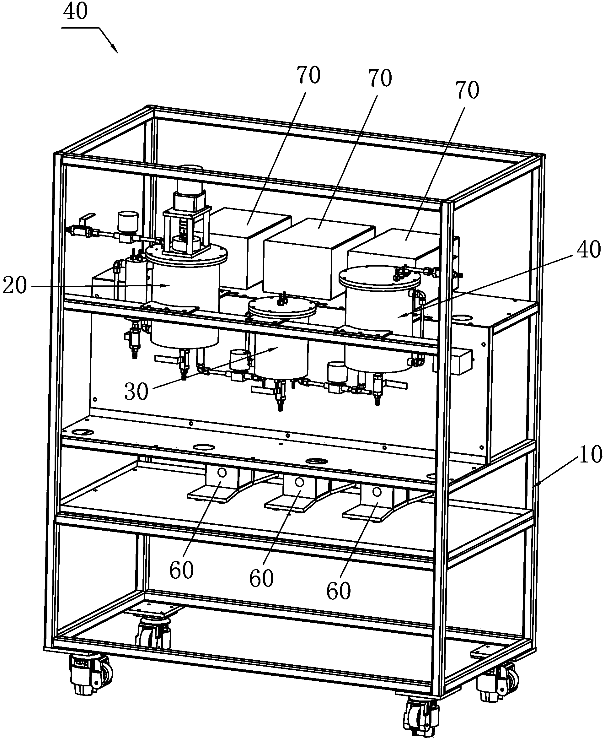
[0042] Please refer to Figure 1 to Figure 5 As shown, it has shown the specific structure of the preferred embodiment of the present invention, the electrolytic solution vacuum agitation degassing device with automatic cleaning function includes a main controller (not shown in the figure), a vacuum agitation device 20, The liquid storage device 30, the automatic cleaning device 40 and the liquid injection device 50 are equipped with a liquid injection pump 60 and a liquid injection pump 60 for controlling the liquid injection frequency and the liquid injection volume for the liquid storage device 30 toward the liquid injection device. pump controller 70 .

[0043] Wherein, the vacuum stirring device 20 includes an electrolyte degassing barrel 21, a vacuum stirring blade 22 and a vacuum stirring motor 23 for driving the vacuum stirring blade 22, the vacuum stirring motor 23 is located above the electrolyte debubbling barrel 21, the vacuum The stirring blade 22 is located insi...


PUM


Abstract

The invention discloses an electrolyte vacuum stirring bubble-removal device with a self-cleaning function. The device comprises a master controller, a vacuum stirring device, a liquid storage device, a self-cleaning device and a liquid injection device. In allusion to the liquid injection motion of the liquid storage device towards the liquid injection device, a liquid injection pump and a liquid injection pump controller for controlling liquid injection frequency and liquid injection amount is configured. Through the arrangement and cooperation of the vacuum stirring device and the liquid storage device, double electrolyte bubble-removal processing is carried out in the vacuum stirring device and the liquid storage device. Under the action of the liquid injection pump controller and the liquid injection pump, the bubble-removed electrolyte is accurately injected to the liquid injection device according to corresponding liquid injection frequency and liquid injection amount. Thus, it is ensured that there is no bubble in the electrolyte in a battery. The self-cleaning device can be used to automatically clean the liquid injection pump, the liquid storage device and the liquid injection device, so as to prevent crystallization and solidification of residual electrolyte. Thus, stability and reliability of subsequent liquid injection process are not influenced. The device provided by the invention has high degree of automation and is easy to operate and manage.

Description

technical field [0001] The invention relates to the technology in the field of battery production equipment, in particular to an electrolyte vacuum stirring and debubbling device with an automatic cleaning function. Background technique [0002] When making a lithium battery, the positive electrode, the negative electrode and the separator are usually made into a pole core, and then the pole core is put into the battery shell and covered with a cover plate; usually, a liquid injection hole is provided on the cover plate, through which the The liquid injection hole injects the electrolyte into the battery. The quality of the electrolyte and the amount of liquid injection directly determine the quality of the lithium battery. [0003] In the existing battery production process, more air bubbles are generated in the liquid injection pipeline, that is, there will be more air bubbles in the electrolyte, which often leads to dripping and unstable injection accuracy during liquid i...

Claims


Application Information

Patent Timeline
Patent Type & Authority Applications(China)
IPC IPC(8): H01M2/36H01M10/058H01M50/609H01M50/673
CPCH01M10/058H01M50/60Y02E60/10Y02P70/50
Inventor 喻世民王聪肖江连周元才
Owner DONGGUAN HONBRO LI BATTERY EQUIP TECH
Why Eureka
Try Eureka