
A contour fillet automatic control deburring device

A deburring and filleting technology, applied in the direction of manufacturing tools, grinding feed movement, grinding workpiece support, etc., can solve the problems of low grinding accuracy, affect the use of workpieces, affect the accuracy of parts and use requirements, and achieve grinding accuracy High, prevent left and right tilt, uniform force effect

Active Publication Date: 2017-05-17
苏州锃道研磨技术有限公司
View PDF5 Cites 0 Cited by
  • Summary
  • Abstract
  • Description
  • Claims
  • Application Information

AI Technical Summary

Problems solved by technology

[0003] At present, almost all metal parts processing factories use a lot of manpower to remove the burrs formed during the stamping process of metal sheets. This manual deburring method often relies on manual use of toothbrushes and repeated friction on the surface of the workpiece. Not only labor High strength, low efficiency, and easy to cause damage to parts, affecting the accuracy and use requirements of parts
In addition, a deburring device is also disclosed in the prior art. By setting a grinding groove under the grinding device, the wear of the upper grinding device and the conveyor belt below for conveying workpieces is reduced, and the service life is prolonged. However, when the upper grinding device grinds When the workpiece is on one side, the workpiece is easy to tilt left and right, resulting in uneven grinding of the side R angle, low grinding accuracy, and affecting the later use of the workpiece

Method used


Image

  • A contour fillet automatic control deburring device
  • A contour fillet automatic control deburring device
  • A contour fillet automatic control deburring device

Examples


Embodiment

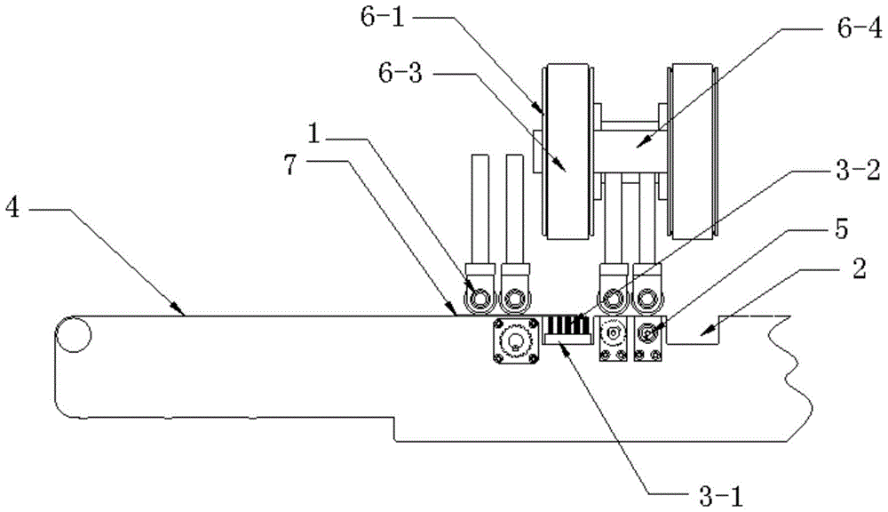
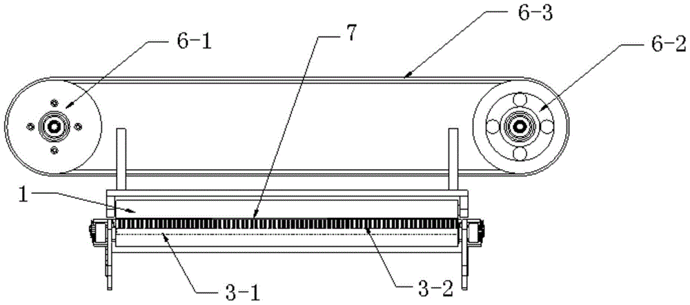
[0019] Example: refer to figure 1 , 2 As shown, a contour fillet automatic control deburring device includes a workpiece transmission mechanism and a burr grinding mechanism. roller wheel) and a grinding device corresponding to the rear side of each group of pressing roller device 1 and whose grinding direction is perpendicular to the conveying direction of the workpiece conveying mechanism. A strip-shaped grinding groove 2 is provided directly below each grinding device. At the same time, a support component is provided in the bar-shaped grinding groove 2 .

[0020] refer to image 3 As shown, the support member of the present invention includes a fixed base 3-1 located at the bottom of the bar-shaped grinding groove 2, and a support brush 3-2 evenly arranged on the fixed base 3-1, and the top of the support brush 3-2 is connected to the bar. The top of the grinding groove 2 is parallel to the top, and the support brush 3-2 cooperates with the grinding brush (not shown in ...


PUM


Abstract

The invention discloses an automatic control burring device for a profile circular bead. The automatic control burring device comprises a workpiece conveying mechanism and a bur polishing mechanism and is characterized in that the bur polishing mechanism comprises multiple groups of compression roller devices and polishing devices, wherein the compression roller devices are arranged above the workpiece conveying mechanism, each polishing device is arranged on the rear side of the corresponding compression roller device, and the polishing direction of the polishing devices is perpendicular to the conveying direction of the workpiece conveying mechanism. A strip-shaped polishing groove is formed right below each corresponding polishing device, and a supporting part is arranged in the corresponding strip-shaped groove. The automatic control burring device has the advantages that the supporting parts are arranged in the strip-shaped grooves, so that lateral inclination of long strip-shaped workpieces in the polishing process is prevented effectively, and high polishing accuracy of R corners on the lateral sides of the workpeices is ensured.

Description

technical field [0001] The invention relates to a deburring device, in particular to a contour fillet automatic control deburring device. Background technique [0002] Most of the mechanical parts are formed by stamping. On the exit side of the tool, there will be burrs to varying degrees, which will affect the quality of further processing. These burrs must be removed before painting or finishing the workpiece. [0003] At present, almost all metal parts processing factories use a lot of manpower to remove the burrs formed during the stamping process of metal sheets. This manual deburring method often relies on manual use of toothbrushes and repeated friction on the surface of the workpiece. Not only labor The strength is high, the efficiency is low, and it is easy to cause damage to the parts, affecting the accuracy and use requirements of the parts. In addition, a deburring device is also disclosed in the prior art. By setting a grinding groove under the grinding device,...

Claims


Application Information

Patent Timeline
Patent Type & Authority Patents(China)
IPC IPC(8): B24B9/04B24B41/06
CPCB24B9/04B24B41/005B24B41/06
Inventor 孙毅
Owner 苏州锃道研磨技术有限公司
Learn More