
Keyboard with support

A keyboard and key shaft technology, applied in the input/output process of data processing, input/output of user/computer interaction, instruments, etc., can solve the problem that the tilt angle of the keyboard cannot be adjusted, and it is difficult to adapt to everyone's habits, etc., to achieve The effect of improving comfort

Inactive Publication Date: 2018-05-01
四川兴龙腾科技有限公司
View PDF0 Cites 0 Cited by
  • Summary
  • Abstract
  • Description
  • Claims
  • Application Information

AI Technical Summary

Problems solved by technology

[0003] The purpose of the present invention is to provide a keyboard with a bracket to solve the problem that the inclination angle of the existing keyboard cannot be adjusted and it is difficult to adapt to the habits of all people

Method used


Image

  • Keyboard with support
  • Keyboard with support

Examples


Embodiment 1

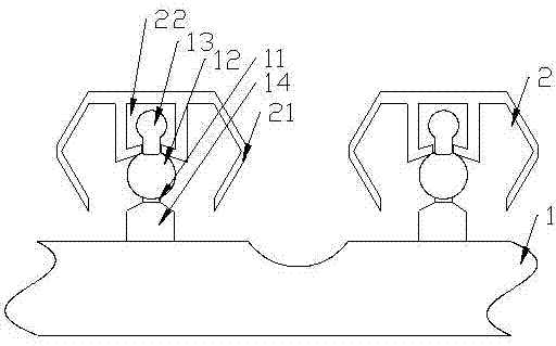
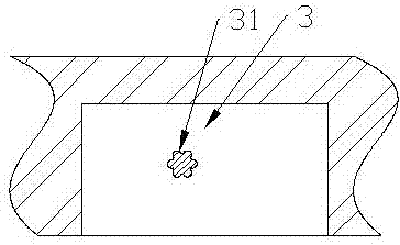
[0024] This embodiment provides a keyboard with a bracket, such as Figure 1-2 As shown, it includes a main body 1, a bracket connected to the main body through a rotating shaft 31 and a button installed on the main body 1. The main body 1 is provided with a mounting hole and a keycap 2 installed in the mounting hole through a key shaft 11. The bottom end of the key shaft 11 is connected to the circuit board in the main body 1, the top end is provided with a limiting block 13, the lower surface of the keycap 2 is provided with a positioning cavity 22, and the limiting block 13 is located in the positioning cavity 22;

[0025] A hollow elastic silicone ball 12 is connected to the lower part of the positioning cavity 22, and the elastic silicone ball 12 is set on the key shaft 11 and has an air port on the lower side;

[0026] The lower surface of the main body is provided with a groove 3 for placing a bracket, and a group of side walls of the groove 3 are relatively provided wi...

Embodiment 2

[0029] In this embodiment, on the basis of Embodiment 1, it is further defined that: the elastic silicone ball 12 is fixedly connected to the bottom end of the positioning cavity 22, and the positioning cavity 22 communicates with the outside through an air port.

[0030] The elastic silicone ball 12 has only one outlet below, which prevents air leakage from causing insufficient blowing force and cannot blow away dust.

Embodiment 3

[0032] On the basis of Embodiment 1, this embodiment further defines: the main body is provided with a mounting block 14, the mounting hole passes through the mounting block 14, and the top surface of the mounting block, 14 gradually decreases from the mounting hole to the edge .

[0033] The gas leaving from the elastic silicone ball 12 can smoothly blow away the dust near the installation hole.


PUM


Abstract

The invention discloses a keyboard with a support. The keyboard comprises a main body, the support connected on the main body through a rotating shaft and keys arranged on the main body, wherein mounting holes and keycaps arranged in the mounting holes through key shafts are arranged on the main body; the bottom ends of the key shafts are connected with a circuit board in the main body; the top ends of the key shafts are provided with limit blocks; positioning cavities are arranged in the bottom surfaces of the keycaps; the limit blocks are arranged in the positioning cavities; hollow elasticsilicone balls are connected below the positioning cavities; the silicone balls sleeve on the key shafts; air ports are formed below the silicone balls; a groove for placing the support is arranged inthe lower surface of the main body; half holes are oppositely formed in one group of side walls of the groove; more than two limit grooves along the axial directions of the half holes are arranged inthe inner side walls of the half holes; two ends of the rotating shaft are respectively inserted into the half holes; and the section of the rotating shaft is matched with the sections of the half holes in the size and shape aspects. The keyboard disclosed by the invention has the beneficial effects that the inclination degree of the keyboard can be adjusted according to the needs of environmentand users to adapt to more situations and improve the comfortable sensation of the users.

Description

technical field [0001] The invention relates to the field of computer peripherals, in particular to a keyboard with a bracket. Background technique [0002] The keyboard is the most commonly used and most important input device, through which English letters, numbers, punctuation marks, etc. can be input into the computer, so as to issue commands and input data to the computer. However, according to the environment in which the keyboard is used and the habits of people, it is necessary to adjust the inclination of the keyboard, but the support of the existing keyboard only has two states: open and closed, that is, the keyboard only has two states, horizontal and inclined, and the angle cannot be adjusted. . Contents of the invention [0003] The purpose of the present invention is to provide a keyboard with a bracket, which solves the problem that the inclination angle of the existing keyboard cannot be adjusted and it is difficult to adapt to the habits of all people. ...

Claims


Application Information

Patent Timeline
IPC IPC(8): G06F3/02
CPCG06F3/0208G06F3/0202
Inventor 黄永
Owner 四川兴龙腾科技有限公司
Learn More