
Connecting sleeve parison tube double-sided milling machine

A technology for connecting sleeves and blank tubes, applied in the field of machinery, can solve problems such as low efficiency, insufficient smoothness, and texture generation

Active Publication Date: 2014-11-26
保定森源建筑机械有限责任公司
View PDF9 Cites 5 Cited by
  • Summary
  • Abstract
  • Description
  • Claims
  • Application Information

AI Technical Summary

Problems solved by technology

The current milling and flattening process generally uses the radial feeding method of the machine tool to mill and flatten the side of the connecting sleeve blank tube from the outside to the inside by point cutting. This working method is too inefficient and will produce texture, not smooth enough

Method used


Image

  • Connecting sleeve parison tube double-sided milling machine
  • Connecting sleeve parison tube double-sided milling machine
  • Connecting sleeve parison tube double-sided milling machine

Examples


Embodiment Construction

[0018] The present invention will be further described below. The device includes a base, a feeding mechanism, a clamping mechanism and a knife-feeding mechanism:

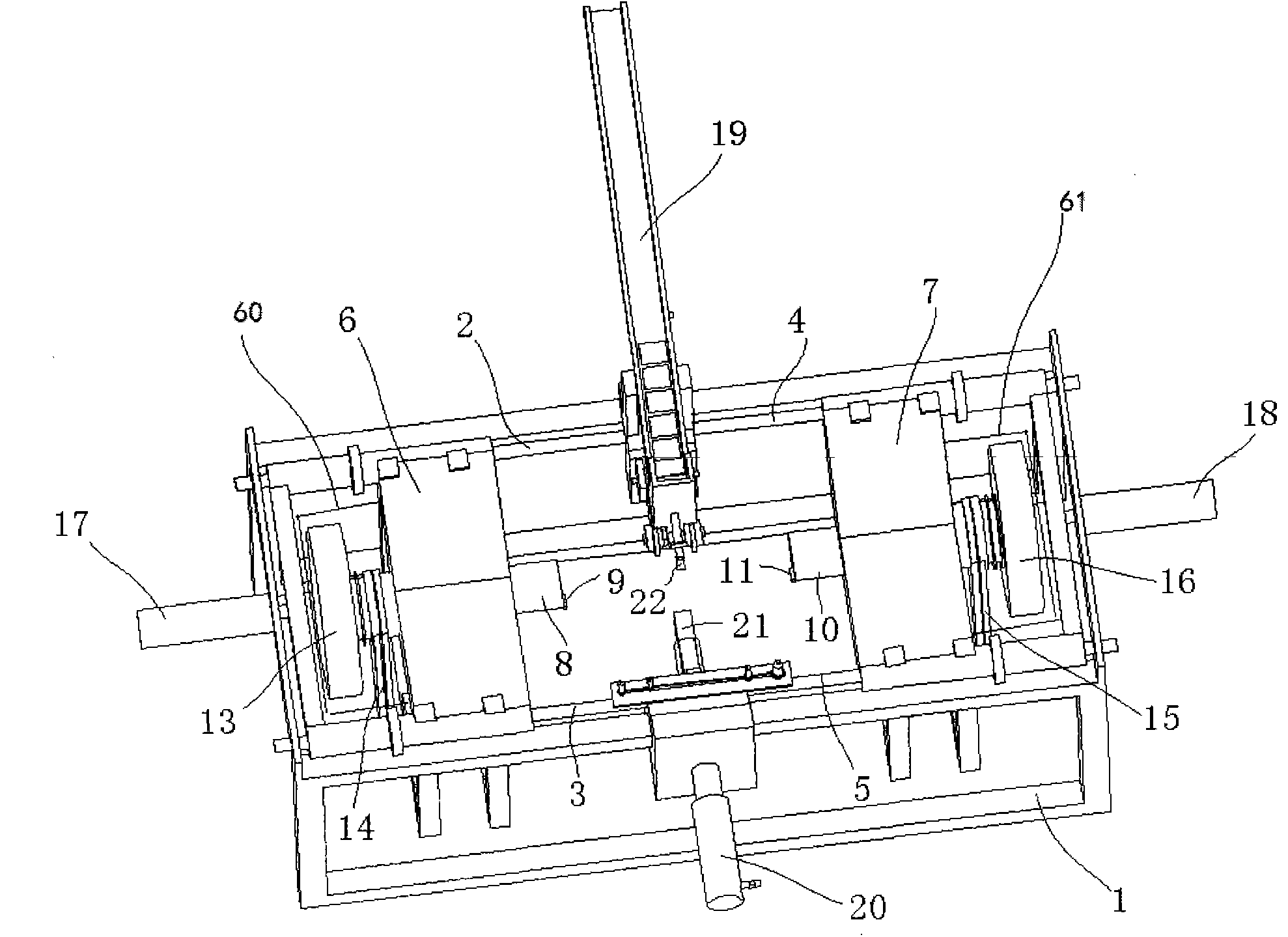
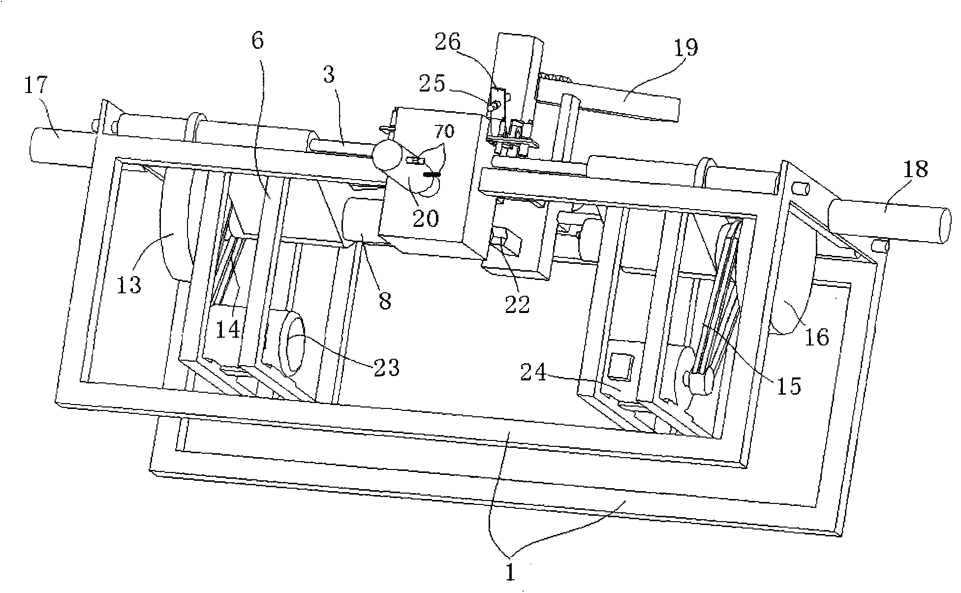
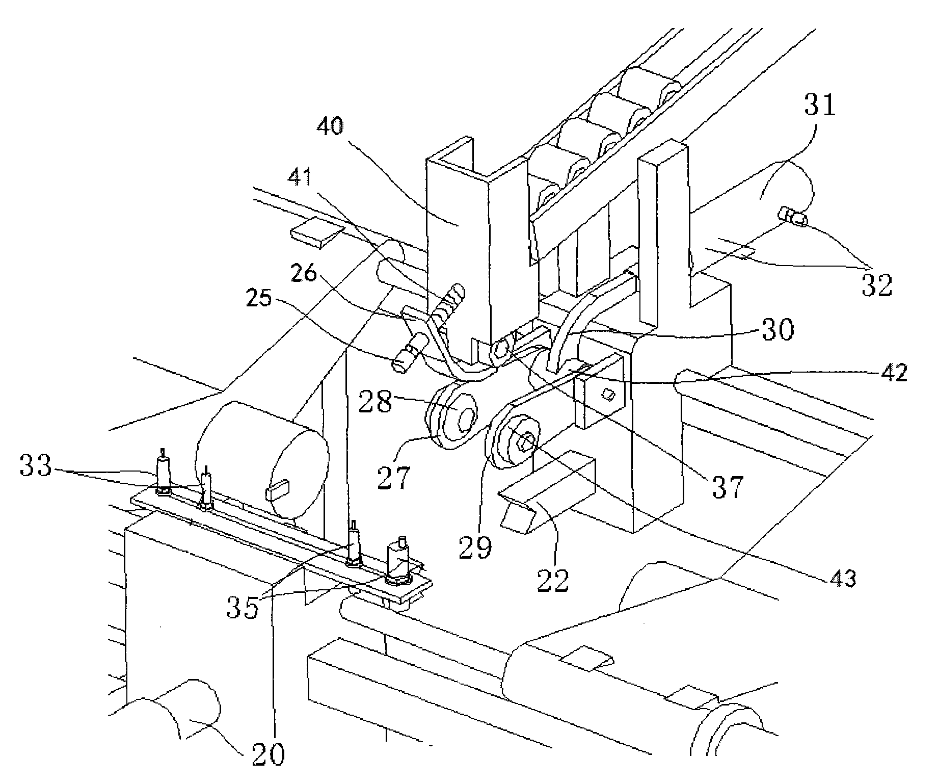
[0019] Such as figure 1 , figure 2 and image 3 As shown, the base 1 is a rectangular three-dimensional support, and the feeding mechanism is located above the middle of the base 1, including an inclined feeding track 19, in which the connecting sleeve blank tube can be placed, and the connecting sleeve blank tube can slide downward by its own gravity. The bottom of the feeding track 19 is connected with the discharge port 40, and a connecting rod 25 is installed on the outside of the discharge port 40, which is inclined downward. The connecting rod 25 is covered with an elastic clamping plate 26, and the connecting rod 25 is covered with a spring 41 to support the discharge. Between the outer wall of the opening 40 and the elastic clamping plate 26, the lower end of the elastic clamping plate 26 is located belo...


PUM


Abstract

The invention discloses a connecting sleeve parison tube double-sided milling machine. The milling machine mills two side surfaces of a connecting sleeve parison tube through automatically conveying the connecting sleeve parison tube to a clamping mechanism by a feeding mechanism and driving a slice knife by knife feeding mechanisms at two sides. The milling machine can mill the two side surfaces of the connecting sleeve parison tube in a surface cutting manner, and realizes high smoothness of the side surfaces, and energy saving and high efficiency in the work process.

Description

technical field [0001] The invention relates to the field of machinery, in particular to a double-sided milling machine for milling both sides of a connecting sleeve blank tube. Background technique [0002] In industries such as industry, agriculture, construction, and bridges, a large number of connecting sleeves are needed. The connecting sleeve has a screw thread inside, and the two sides are smooth, and other rods can be connected together through the connecting sleeve. In the production process of the connecting sleeve, the seamless steel pipe can be used as the raw material, and the seamless steel pipe is cut into sections to obtain the connecting sleeve blank tube, and then the side of the connecting sleeve blank tube is milled flat, and then tapped; the method of forging can also be used , the cast iron is forged, high-temperature perforated, and the surface is peeled off to obtain the connected sleeve blank tube, and then both sides are milled and tapped. Therefor...

Claims


Application Information

Patent Timeline
IPC IPC(8): B23C1/04B23Q5/10B23Q5/26B23Q15/22
Inventor 李洪明
Owner 保定森源建筑机械有限责任公司
Learn More