Composite cooling device

A technology of heat dissipation device and heat dissipation unit, applied in the direction of cooling/ventilation/heating transformation, etc., can solve the problem of uneven heat dissipation of multiple LED chips, and achieve the effect of excellent heat transfer ability and good temperature uniformity and heat dissipation.

Inactive Publication Date: 2017-10-13
UNIV OF SHANGHAI FOR SCI & TECH +1
View PDF4 Cites 0 Cited by
  • Summary
  • Abstract
  • Description
  • Claims
  • Application Information

AI Technical Summary

Problems solved by technology

The disadvantage of this invention is that there are gaps between the flat heat pipes, resulting in uneven heat dissipation of multiple LED chips placed on it

Method used


Image

  • Composite cooling device
  • Composite cooling device
  • Composite cooling device

Examples


Embodiment Construction

[0022] The specific implementation manners of the present invention will be described below in conjunction with the accompanying drawings.

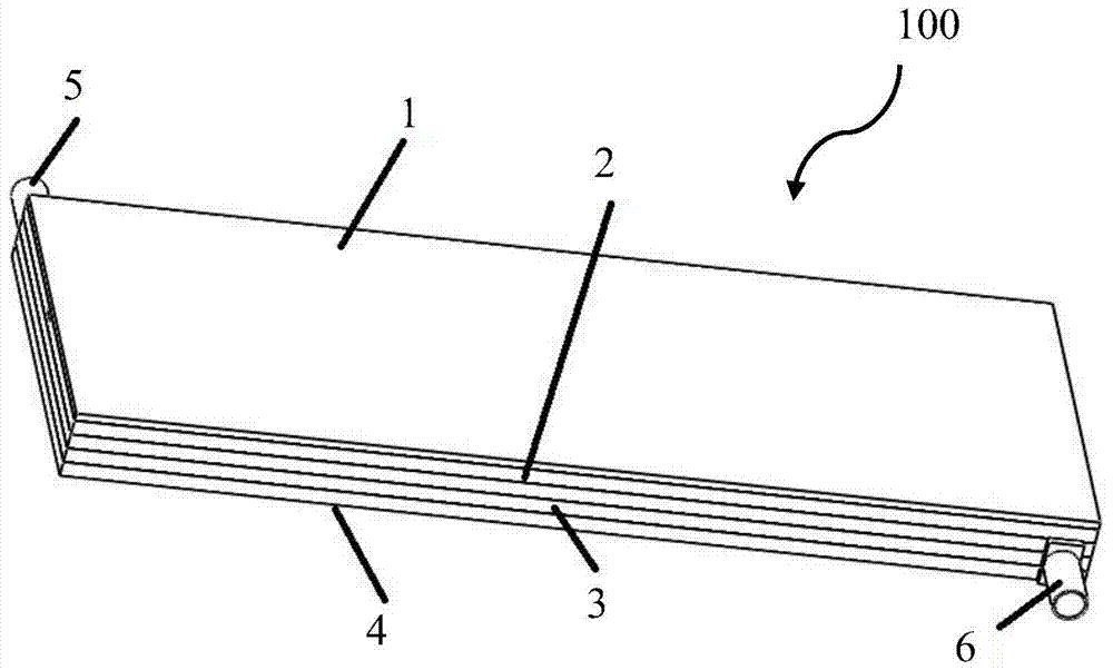
[0023] figure 1 It is a schematic diagram of the appearance structure of the composite heat sink in the embodiment.

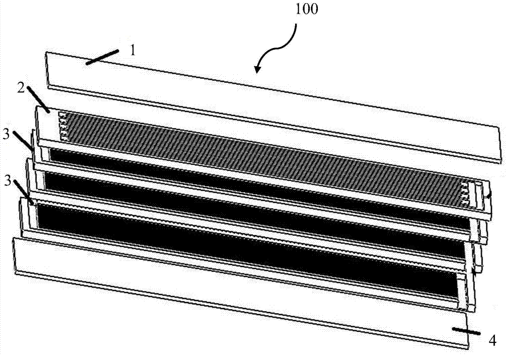
[0024] figure 2 It is a schematic diagram of the exploded structure of the composite heat sink in the embodiment.

[0025] like figure 1 and figure 2 As shown, the composite heat dissipation device 100 includes a cover plate 1, a first heat dissipation unit 2, a second heat dissipation unit 3, a bottom plate 4, and a mass-incoming unit 5 and a mass-exiting unit 6 located on both sides of the second heat dissipation unit 3, the cover plate 1 and the The bottom plate 4 covers the upper end of the first heat dissipation unit 2 and the lower end of the second heat dissipation unit respectively, and the mass-incoming unit 5 and the mass-exiting unit 6 are all connected to the condenser outside the compound heat dissipatio...


PUM


Abstract

The invention provides a composite heat radiating device. The composite heat radiating device comprises a first heat radiating unit which is formed by carving at least one pipeline with a capillary structure in a flat plate, a second heat radiating unit which is located below the first heat radiating unit, and comprises a second heat radiating pipeline which is formed by arranging a number of micro channels, a cover plate and a bottom plate, wherein the cover plate and the bottom plate cover the upper end and the lower end of the composite heat radiating device. Due to the fact that the first heat radiating unit is a pulsating heat pipe, heat dissipated by a number of chips can be rapidly spread to the first heat radiating unit in the sustained oscillation phase change process, and a uniform temperature effect is realized. The first heat radiating unit and the second heat radiating unit are organically combined, so that heat is transferred to the lower second heat radiating unit. Heat is taken away by a refrigerant of the second heat radiating unit. Two heat radiating units are organically combined. The composite heat radiating device provided by the embodiment has the advantages of simple structure and improved heat radiating uniformity.

Description

technical field [0001] The invention belongs to the field of heat dissipation of electronic devices, and in particular relates to a composite heat dissipation device. Background technique [0002] Since the development of integrated circuits, heat dissipation design has become one of the key technologies in the structural design of electronic equipment. With the increasing integration of electronic devices and system equipment, integrated circuits are developing towards high density and high power, which increases the number of chips, increases the heat flux density, and reduces the space for heat dissipation. When dissipating heat for multiple electronic components at the same time, the heat dissipation system cannot spread the heat evenly, and the corresponding heat cannot be quickly diffused to the entire micro-channel cold plate or flat-plate oscillating heat pipe, resulting in uneven heat dissipation of multiple electronic components. Therefore, a single heat dissipati...

Claims


Application Information

Patent Timeline
Patent Type & Authority Patents(China)
IPC IPC(8): H05K7/20
Inventor 崔晓钰邱子骞张昊段威威隋缘
Owner UNIV OF SHANGHAI FOR SCI & TECH
Why Eureka
Try Eureka