
New concept broadband circularly polarized antenna

A circularly polarized antenna, a new concept technology, applied in the microwave field, can solve the problems of difficulty in determining a wide frequency band, good full-plane performance, high manufacturing process requirements, and high manufacturing costs, and achieves novel structure, full-plane antenna structure, Create easy effects

Active Publication Date: 2014-11-19
SOUTH CHINA UNIV OF TECH
View PDF5 Cites 20 Cited by
  • Summary
  • Abstract
  • Description
  • Claims
  • Application Information

AI Technical Summary

Problems solved by technology

However, this method has a complex structure, a large volume, and high manufacturing process requirements.
There is also an L-type probe coupling feed, but this method generally requires an external matching circuit, and is generally a double-feed form, with a complex structure and high production costs.
[0005] On the whole, it is difficult for the existing wideband circularly polarized antenna technology to achieve better performance in the three aspects of fixed bandwidth and full plane.

Method used


Image

  • New concept broadband circularly polarized antenna
  • New concept broadband circularly polarized antenna
  • New concept broadband circularly polarized antenna

Examples


Embodiment

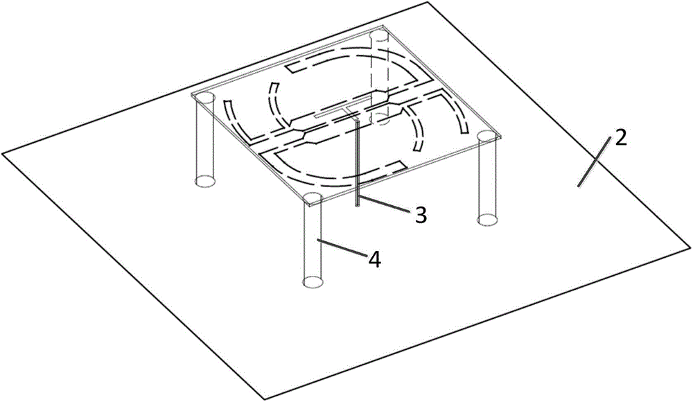
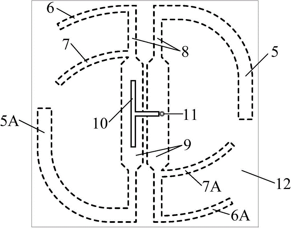
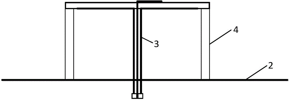
[0030] Such as figure 1 , figure 2 As shown, a new concept broadband circularly polarized antenna includes an antenna radiation unit, a dielectric substrate 12, a reflector 2 and a feeder 3, the feeder 3 is connected to the antenna radiation unit, and the antenna radiation unit is etched on the dielectric substrate 12 , the dielectric substrate 12 is horizontally fixed above the reflection plate through a support structure 4, the support structure 4 is made of insulating material, and its height is 0.1λ˜0.5λ, where λ is the wavelength corresponding to the free space frequency of 2.2GHz, The height of the support structure depends on the distance between the antenna radiation unit and the reflector 2, and the material can be plastic or wooden rods. The support structure of this embodiment includes four wooden rods, which are respectively located at the four corners of the dielectric substrate. The height of the wooden rods is 41mm.

[0031] The antenna radiating unit include...


PUM


Abstract

The invention discloses a new concept broadband circularly polarized antenna. The new concept broadband circularly polarized antenna adopts the structure that a feed line is connected with an antenna radiation unit; the antenna radiation unit is etched on a dielectric baseplate; the dielectric baseplate is horizontally fixed above a reflecting plate through a supporting structure; the antenna radiation unit comprises two bending oscillators, two parasitic units, a coplanar microstrip line and a T-shaped microstrip line feed structure; the bending oscillators, the parasitic units and the coplanar microstrip line are etched on the reverse side of the dielectric baseplate; the T-shaped microstrip line feed structure is etched on the obverse side of the dielectric baseplate; the two bending oscillators are centrosymmetric about the dielectric baseplate; the coplanar microstrip line is arranged at a medial axis of the dielectric baseplate; the coplanar microstrip line comprises two wide-gap coplanar microstrip line bodies and two narrow-gap microstrip line bodies; the wide-gap coplanar microstrip line bodies feed the bending oscillators respectively to stimulate circularly polarized waves through the non-center-fed bending oscillators; besides, the broadband circularly polarized antenna adopts a novel and simple full-plane structure, and is convenient to process and form.

Description

technical field [0001] The invention relates to the field of microwave technology, in particular to a new concept broadband circularly polarized antenna. Background technique [0002] The application of circularly polarized antennas in wireless communication systems has attracted more and more attention, because circularly polarized antennas can not only reduce multipath effects but also receive incoming waves with arbitrary polarization, and directional circularly polarized antennas can provide both High security, while improving channel utilization. In addition, if the antenna radiates left-handed circularly polarized waves, it will only receive left-handed circularly polarized waves but not right-handed circularly polarized waves; The rotation orthogonality of circularly polarized antennas can be used to improve communication capacity in polarization diversity work. When the circularly polarized wave is incident on a symmetrical target (such as a plane, a spherical surf...

Claims


Application Information

Patent Timeline
Patent Type & Authority Applications(China)
IPC IPC(8): H01Q1/38H01Q1/50H01Q19/10H01Q21/24
Inventor 李融林潘利军崔悦慧
Owner SOUTH CHINA UNIV OF TECH
Learn More