
Local postweld heat treatment method for three-way branch pipe butt joint

A technology for butt joints and post-heat treatment, applied in heat treatment furnaces, heat treatment equipment, furnaces, etc., which can solve problems such as deteriorating temperature field, adverse effects on joint performance and life, and joint scrapping.

Active Publication Date: 2014-11-19
SUZHOU NUCLEAR POWER RES INST +2
View PDF5 Cites 7 Cited by
  • Summary
  • Abstract
  • Description
  • Claims
  • Application Information

AI Technical Summary

Problems solved by technology

This empirical method often makes the highest temperature point not exactly located on the weld, and it is difficult to avoid the circumferential temperature difference
The excursion of the maximum temperature and the existence of the circumferential temperature difference deteriorate the temperature field of the post-weld heat treatment of the joint, increase the residual stress of the joint after heat treatment, and have an adverse effect on the service performance and life of the joint; when the maximum temperature of the deviation exceeds the material After the phase transition point, the material recrystallizes, causing serious damage to the performance of the joint, and even directly leading to the scrapping of the joint

Method used


Image

  • Local postweld heat treatment method for three-way branch pipe butt joint
  • Local postweld heat treatment method for three-way branch pipe butt joint
  • Local postweld heat treatment method for three-way branch pipe butt joint

Examples


Embodiment Construction

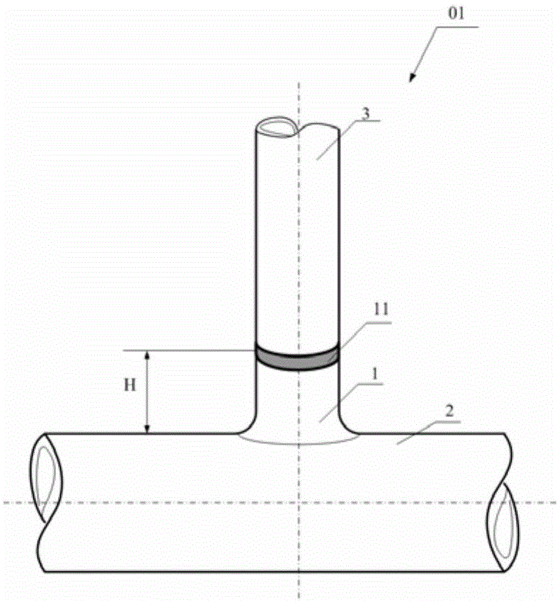
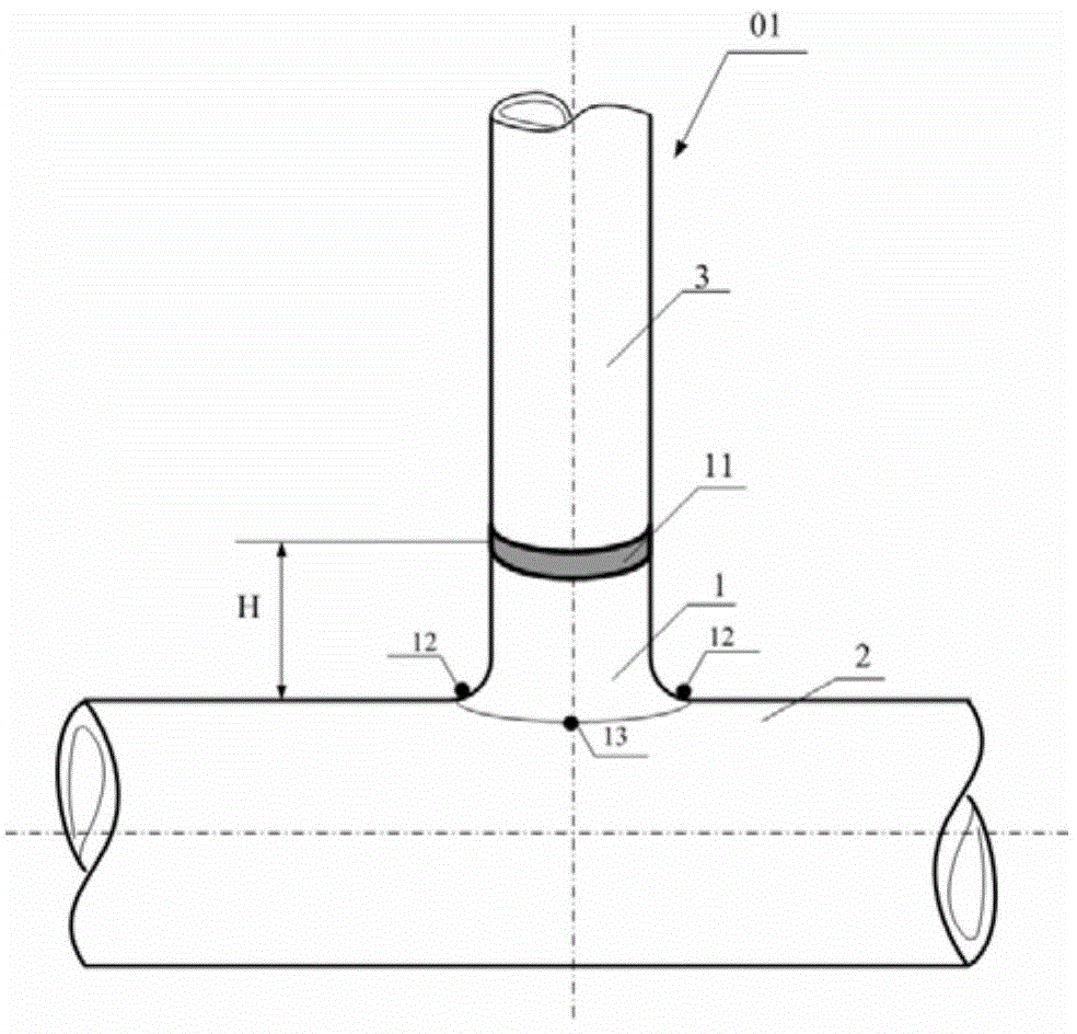
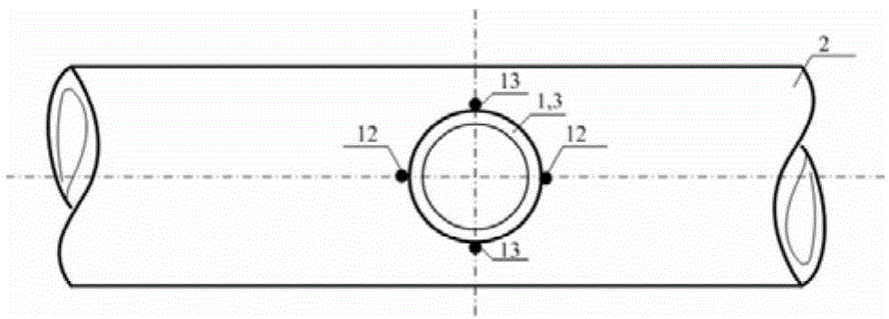
[0059] Such as Figure 1 to 6 As shown, the butt joint 01 of the three-way branch pipe includes a weld 11 connecting the branch pipe 1, the main pipe 2, the pipe 3, the branch pipe 1 and the pipe 3. When performing post-weld heat treatment on the butt joint 01 of the three-way branch pipe, the main heating device 21 (heating rope, heating plate, etc.) shall be symmetrically arranged at the two ends of the welding seam 11 with equal power and equal width, and the layout width of each end is equal to the branch pipe 1. The height H. A thermocouple is arranged at the welding seam position 24 opposite to the apex 13 of the three-way abdomen as the temperature control thermocouple 20 of the main heating device 21. At the end of the main heating device, a thermocouple is set at a position 23 opposite to the apex of the tee abdomen, which serves as the temperature measuring thermocouple 22 at the end of the main heating device 21; with the branch pipe 1 as the center, the auxiliary h...


PUM


Abstract

The invention relates to a local postweld heat treatment method for a three-way branch pipe butt joint. The method mainly adopts a main heating device and an auxiliary heating device to heat the three-way branch pipe butt joint simultaneously. The heating elements of the main heating device are symmetrically arranged at two ends of a weld joint in an equi-power and equi-width way; the width of arrangement of the heating elements at each end is equal to the height of a branch pipe; temperature control thermocouples are arranged on the weld joint at positions corresponding to the abdomen peaks of a tee pipe; a heat treatment curve is set according to given postweld heat treatment process parameters. The heating elements of the auxiliary heating device are arranged on a main pipe by taking the branch pipe as a center; temperature control thermocouples are arranged on the shoulder peaks of the tee pipe; the real-time temperature control temperature of the auxiliary heating device is the real-time temperature plus or minus 10 DEG C at the positions, corresponding to the abdomen peaks of the tee pipe, on the branch pipe at the end parts of the main heating device, which is obtained when the main heating device is used for heating. The method provided by the invention effectively avoids the phenomenon that the maximum-temperature point in a heating area deviates from the weld joint, reduces circumferential temperature difference of the weld joint, overcomes adverse effects of the traditional postweld heat treatment method, and meets the technical requirements of joint postweld heat treatment.

Description

Technical field [0001] The invention relates to a local post-weld heat treatment method for a butt joint of a tee branch pipe, which is particularly suitable for the local post-weld heat treatment of a butt joint of a T-shaped tee branch pipe. Background technique [0002] Post-weld heat treatment is a kind of heat treatment to eliminate the residual stress of the welded joint and improve the structure and performance of the welded joint. The general process is: install thermocouple → arrange heating device → set heat treatment parameters → wrap insulation cotton → perform heat treatment . [0003] The tee is an important connecting part of the piping system. When post-weld heat treatment is required after welding with the external pipeline at the service site, usually only partial post-weld heat treatment can be performed. One end of the butt joint is connected to an external pipe and the other end is connected to a tee. Therefore, the heat dissipation conditions at both ends of ...

Claims


Application Information

Patent Timeline
Patent Type & Authority Applications(China)
IPC IPC(8): C21D9/50
Inventor 陈忠兵孙志强汤淳波张苏闽吕一仕
Owner SUZHOU NUCLEAR POWER RES INST
Learn More