
Active type direct-current system insulation resistor detection method

A technology of insulation resistance and DC system, which is applied in the direction of measuring resistance/reactance/impedance, measuring devices, measuring electrical variables, etc. It can solve the problems of inability to realize real-time monitoring of insulation resistance status, reduce the insulation performance of equipment, and reduce the safety of personnel and equipment, etc. question

Inactive Publication Date: 2014-11-12
CENT SOUTH UNIV
View PDF0 Cites 24 Cited by
  • Summary
  • Abstract
  • Description
  • Claims
  • Application Information

AI Technical Summary

Problems solved by technology

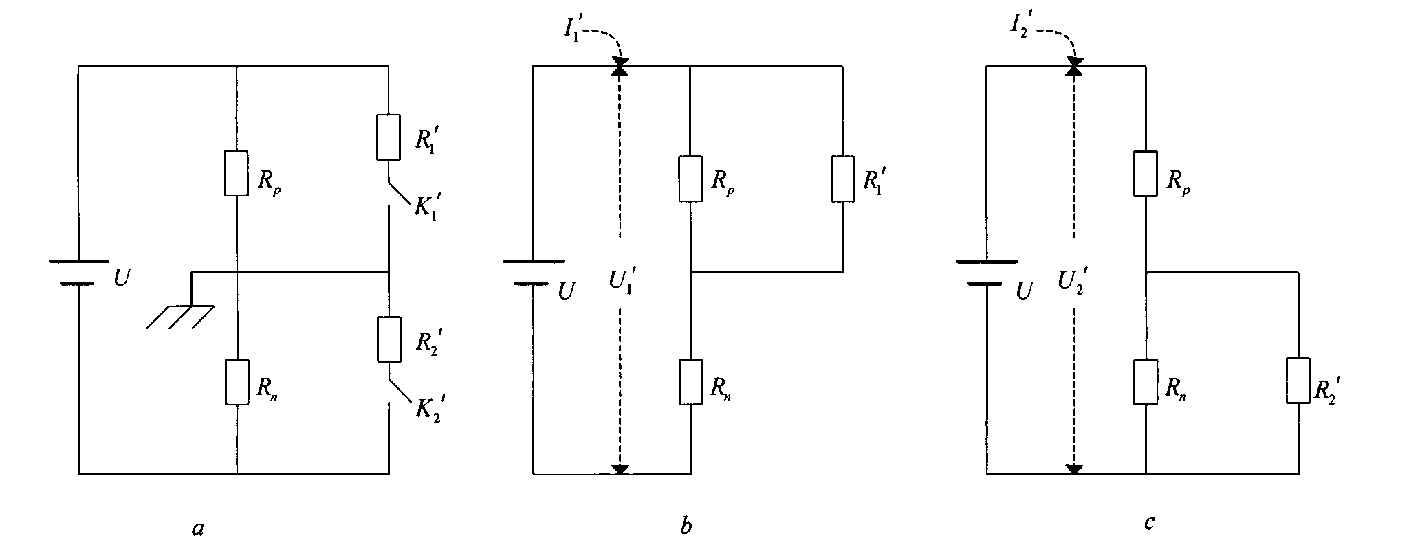
[0012] Problems in the external resistance switching method: 1. Close the switch K 1 ’ or close the switch K 2 ′, the parallel access resistance will reduce the insulation performance of the equipment, thus increasing the danger of operators and equipment; 2. It does not have the real-time monitoring function of insulation resistance
[0015] Problems in the balanced bridge method: 1. Close the switch K at the same time 1 ', K 2 ′, the parallel access resistance will reduce the insulation performance of the equipment, thus reducing the safety of personnel and equipment; 2. In the insulation resistance R p , R n When it is lowered at the same time, the insulation resistance fault cannot be detected; 3. It does not have the real-time monitoring function of insulation resistance
[0016] To sum up, the traditional insulation resistance detection method cannot realize the real-time monitoring of the insulation resistance state.

Method used


Image

  • Active type direct-current system insulation resistor detection method
  • Active type direct-current system insulation resistor detection method
  • Active type direct-current system insulation resistor detection method

Examples


Embodiment Construction

[0052] Hereinafter, the present invention will be further described in detail with reference to the accompanying drawings and specific embodiments, and the specific flow of the method implementation will be described:

[0053] Circuit design:

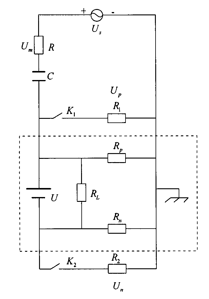
[0054] The insulation resistance detection of this method belongs to the insulation resistance detection of active DC system, image 3 It is the equivalent circuit of the active insulation resistance detection principle. The virtual box in the figure is the actual operating circuit part, U is a high-voltage DC voltage source, R L Is the load, R p , R n They are the insulation resistance of the positive pole and negative pole of the DC voltage source to the ground. In the actual circuit system, the insulation resistance of the positive pole and the negative pole to the ground are floating, and the equivalent resistance R is used here. p , R n Said. The part outside the dashed box in the figure is the auxiliary measurement circuit added, U s It...


PUM


Abstract

The invention discloses an active type direct-current system insulation resistor detection method. The active type direct-current system insulation resistor detection method is applicable to real-time detection of insulation resistors of a direct-current high-voltage source electrical equipment system. The insulation resistor detection method comprises the two stages of fault detection and insulation resistor calculation. According to the fault detection, a parallel-connection resistance value of the positive and the negative insulation resistors can be calculated by measuring voltage values at the two ends of a measurement resistor, and whether the positive and negative insulation resistors break down or not is judged according to the parallel-connection resistance value. According to the insulation resistor calculation, the resistance values of the positive and negative insulation resistors can be calculated by measuring voltage values at the two ends of an access resistor. The active type direct-current system insulation resistor detection method has the advantages that the fault conditions of the positive and negative insulation resistors can be monitored in real time, the whole load is not affected, and the basis is provided for fault diagnosis of the whole system by calculating the resistance values of the positive and negative insulation resistors.

Description

Technical field [0001] The invention is an insulation resistance detection method of an active DC system, which is suitable for real-time monitoring of the insulation resistance of a DC high-voltage source electrical equipment system, and can perform offline detection after detecting the insulation resistance failure, and calculate the positive and negative insulation The resistance value provides a basis for the fault diagnosis of the entire system. Applicable technical fields such as: insulation resistance detection of battery packs for pure electric vehicles and hybrid vehicles; insulation resistance detection for high-voltage DC systems such as energy storage battery packs. Background technique [0002] The electrical equipment system of the DC high-voltage source runs in a complex working environment. The DC bus is affected by the harsh environment and its insulation performance is reduced, resulting in high leakage current, resulting in the low-voltage equipment of the equi...

Claims


Application Information

Patent Timeline
Patent Type & Authority Applications(China)
IPC IPC(8): G01R27/14G01R31/12
Inventor 胡志坤蒋英明林勇杨为王文祥刘斌
Owner CENT SOUTH UNIV
Learn More