Control method for gas path system of gas chromatograph
A gas chromatograph and gas path system technology, which is applied in the field of gas chromatograph gas path system control, can solve the problems of system stability and rapidity, the large difference from the optimal PID coefficient, etc., and achieve stable gas pressure and flow , The effect of fast closed-loop control
- Summary
- Abstract
- Description
- Claims
- Application Information
AI Technical Summary
Problems solved by technology
Method used
Image
Examples
Embodiment
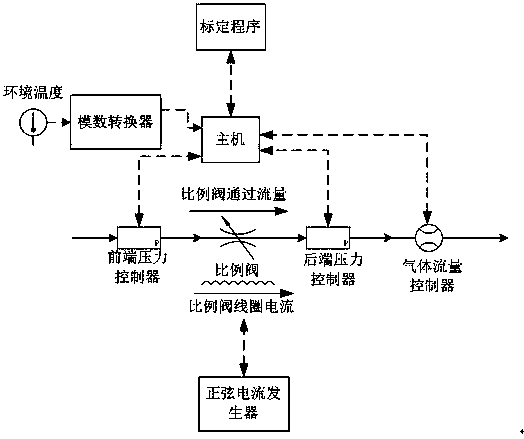
[0034] like Figure 1-2 As shown, the gas path system control method of the gas chromatograph:
[0035] (1) Pre-calibration of the open-loop transfer function of the proportional valve installed in the gas system:
[0036]Firstly, build a hardware platform for calibrating proportional valves. The hardware platform is composed of a host computer with a calibration program, a front-end pressure controller, a back-end pressure controller, and a flow controller. controller, back-end pressure controller and flow controller to stably control the current state of the air path until it meets the calibration requirements, and then send commands to the sinusoidal current generator through the host computer, and sweep the sinusoidal current with different frequencies to the proportional valve coil to obtain the proportional The amplitude and phase information of the valve open-loop transfer function at different frequencies, and then return the measurement results of the open-loop trans...
application example 1
[0043] like image 3 Shown is the working principle diagram of the closed-loop control loop for carrier gas inflow, which is used to control the total flow of carrier gas into the gas chromatograph. The head pressure in this circuit is the cylinder outlet pressure, which can be read from the pressure reducing valve. Backend pressure is the column head pressure, which can be read by a pressure sensor in the split loop in the gas chromatograph. The gas flow is measured by a flow sensor connected in series at the carrier gas inlet. Therefore, when the gas chromatograph is actually working, all the gas parameters of the proportional valve are known values. By querying the calibration table and performing interpolation, the amplitude and phase information of the current open-loop transfer function are obtained, and the PID parameters are corrected.
application example 2
[0045] like Figure 4 Shown is the working principle diagram of the closed-loop control circuit of the purge gas circuit. The front pressure in this circuit is the column head pressure of the gas chromatograph, which is measured by the pressure sensor in the split gas circuit. The back-end pressure is the purge gas pressure, which is measured by a pressure sensor connected in series behind the proportional valve. The gas flow through the proportional valve is the purge flow, which can be calculated from the characteristics of purge gas pressure, atmospheric pressure and air resistance. Therefore, when the gas chromatograph is actually working, all the gas parameters of the proportional valve are known values. By querying the calibration table and performing interpolation, the amplitude and phase information of the current open-loop transfer function can be obtained, and the PID parameters can be corrected.
PUM
 Abstract
Description
Claims
Application Information
 - R&D
- Intellectual Property
- Life Sciences
- Materials
- Tech Scout
- Unparalleled Data Quality
- Higher Quality Content
- 60% Fewer Hallucinations
Browse by: Latest US Patents, China's latest patents, Technical Efficacy Thesaurus, Application Domain, Technology Topic, Popular Technical Reports.
© 2025 PatSnap. All rights reserved.Legal|Privacy policy|Modern Slavery Act Transparency Statement|Sitemap|About US| Contact US: help@patsnap.com


