
Punching material collecting and disc arranging machine

A technology of arranging machines and trays, which is applied in the direction of conveyor objects, transportation and packaging, etc., which can solve the problems of high labor intensity of workers, unusability of arranging machines, and low production efficiency, so as to save manpower, improve production efficiency, compact effect

Active Publication Date: 2014-11-12
GOERTEK INC
View PDF6 Cites 17 Cited by
  • Summary
  • Abstract
  • Description
  • Claims
  • Application Information

AI Technical Summary

Problems solved by technology

For some electronic components, such as shrapnel, etc., the punching speed is often very fast, and the product is small in size or irregular in shape, so the existing plate-setting machine cannot be used
[0003] At present, in actual production, after the punch punches off the shrapnel, the shrapnel falls freely. An ordinary flat belt assembly line is used to pick up and output the material at the bottom of the punch press, and the material is manually collected at one end of the assembly line and placed manually. Not only is the production efficiency low, but Moreover, the labor intensity of workers is high and the production cost is high

Method used


Image

  • Punching material collecting and disc arranging machine
  • Punching material collecting and disc arranging machine
  • Punching material collecting and disc arranging machine

Examples


Embodiment Construction

[0026] In order to make the object, technical solution and advantages of the present invention clearer, the present invention will be further described in detail below in conjunction with the accompanying drawings and embodiments. It should be understood that the specific embodiments described here are only used to explain the present invention, not to limit the present invention.

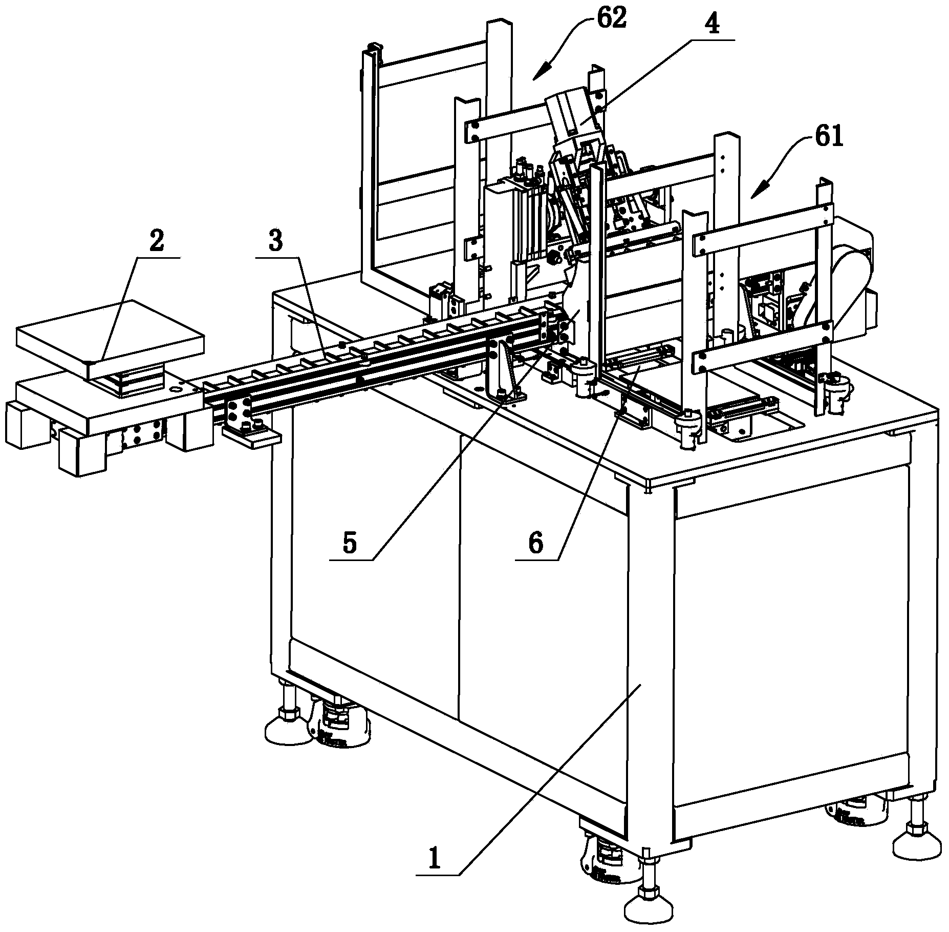
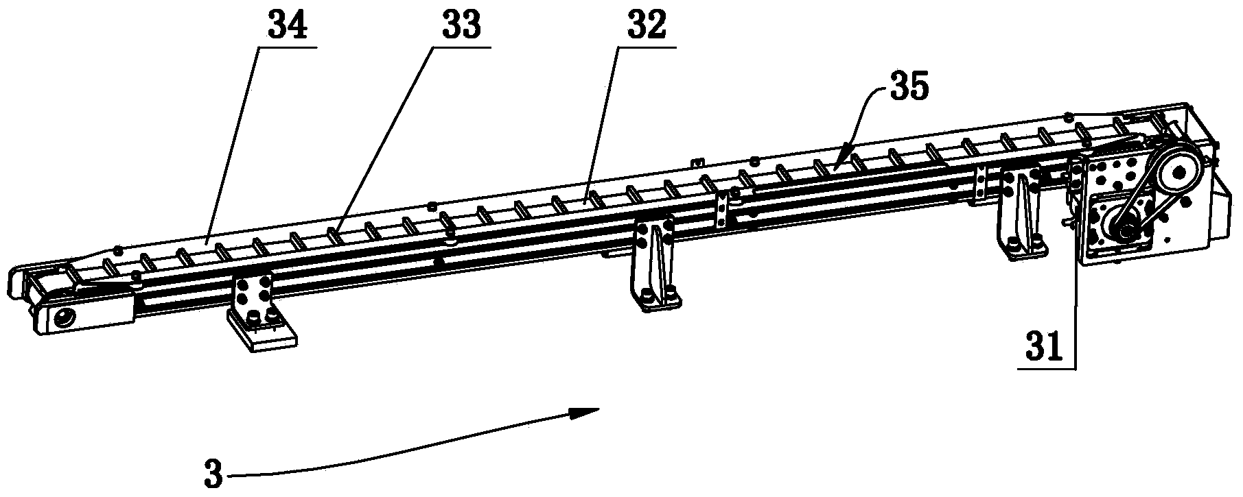
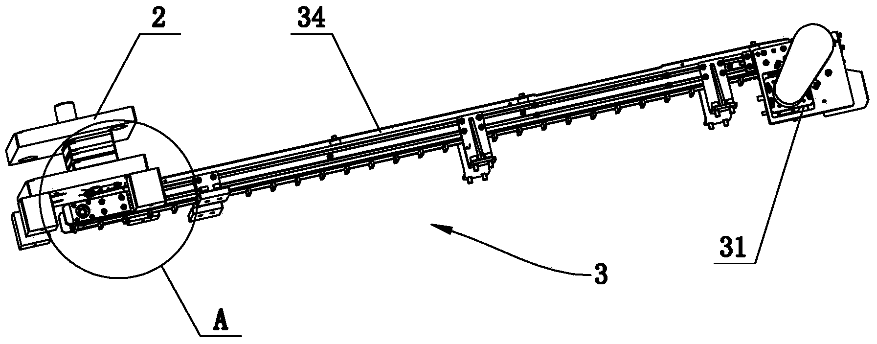
[0027] Such as figure 1 As shown, a stamping receiving and swinging machine is suitable for ferromagnetic materials, including: a frame 1; used to receive the falling materials at the blanking port of the stamping die 2 and realize the material receiving and conveying of the automatic interval and transportation of the materials Mechanism 3, receiving and conveying mechanism 3 is arranged on the frame 1; It is used to absorb the material conveyed by receiving and conveying mechanism 3 and realize the suction and turning mechanism 4 of material turning over and is used to guide the material turned o...


PUM


Abstract

The invention discloses a punching material collecting and disc arranging machine, which belongs to the technical field of element production equipment and comprises a machine frame, a material collecting and conveying mechanism, a suction and turning mechanism, a material guide mechanism and a material disc conveying mechanism, wherein the material collecting and conveying mechanism is used for receiving materials falling down from a material falling opening part of a punching mold and realizing the automatic material partition and conveyance, the suction and turning mechanism is used for sucking the materials conveyed by the material collecting and conveying mechanism and realizing the material turning, the material guiding mechanism is used for guiding the materials turned by the suction and turning mechanism into a material disc, the material disc conveying mechanism is used for conveying the material disc under the material guide mechanism, and the material disc conveying direction of the material disc conveying mechanism is vertical to the material conveying direction of the material collecting and conveying mechanism. The punching material collecting and disc arranging machine has the advantages that the structure is compact, the high-speed automatic material collection and the automatic disc arranging can be realized, the automatic material collecting and disc arranging is realized on the premise of not influencing the original efficiency of a punching machine, the production efficiency can also be improved, the labor is saved, and the cost is reduced.

Description

technical field [0001] The invention belongs to the technical field of component production equipment, and in particular relates to a stamping receiving and swinging machine. Background technique [0002] In the electronics and machinery industries, there are some plate setting machines connected to punching machines, most of which are semi-automatic equipment, which are aimed at products with large size and regular shape, and the punching speed is slow. For some electronic components, such as shrapnel, etc., the punching speed is often very fast, and the product is small in size or irregular in shape, so the existing plate-setting machine cannot be used. [0003] At present, in actual production, after the punch punches off the shrapnel, the shrapnel falls freely. An ordinary flat belt assembly line is used to pick up and output the material at the bottom of the punch press, and the material is manually collected at one end of the assembly line and placed manually. Not only...

Claims


Application Information

Patent Timeline
IPC IPC(8): B65G47/91
Inventor 张磊孙长友
Owner GOERTEK INC
Learn More