
Large-diameter high-temperature-resistant aluminum alloy pipe flanging method and large-diameter high-temperature-resistant aluminum alloy pipe flanging device

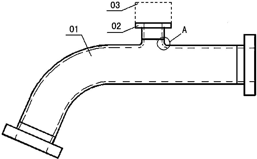
An aluminum alloy tube and large-diameter technology, which is applied in the field of flanging methods and devices for large-diameter heat-resistant aluminum alloy tubes, can solve the problems of difficult quality assurance and heavy workload, and achieve low manufacturing cost, simple manufacturing process, and meet the design requirements. required effect

Inactive Publication Date: 2014-11-12
CHENGDU AIRCRAFT INDUSTRY GROUP
View PDF8 Cites 3 Cited by
  • Summary
  • Abstract
  • Description
  • Claims
  • Application Information

AI Technical Summary

Problems solved by technology

[0003] In order to solve the problems of large-diameter heat-resistant aluminum alloy pipe flanging method in the prior art, such as heavy workload and difficult quality assurance, the present invention proposes a large-diameter heat-resistant aluminum alloy pipe flanging method and device

Method used


Image

  • Large-diameter high-temperature-resistant aluminum alloy pipe flanging method and large-diameter high-temperature-resistant aluminum alloy pipe flanging device
  • Large-diameter high-temperature-resistant aluminum alloy pipe flanging method and large-diameter high-temperature-resistant aluminum alloy pipe flanging device
  • Large-diameter high-temperature-resistant aluminum alloy pipe flanging method and large-diameter high-temperature-resistant aluminum alloy pipe flanging device

Examples


specific Embodiment

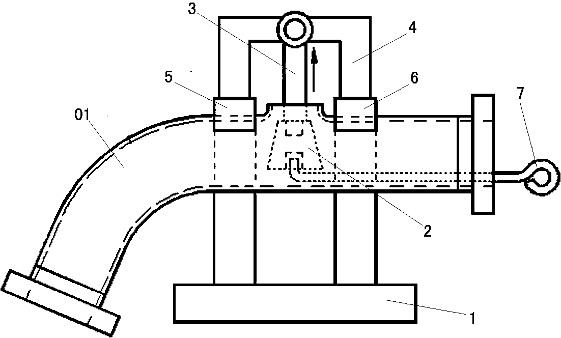
[0031] The method for flanging a large-diameter heat-resistant aluminum alloy pipe of the present invention uses the large-diameter heat-resistant aluminum alloy pipe flanging device of the present invention to flang the aluminum alloy pipe to form a cylindrical nozzle, including the following steps:

[0032] S1. Open an elliptical hole in the radial direction of the aluminum alloy tube, and the long axis direction of the elliptical hole is consistent with the axial direction of the aluminum tube; among them, the long axis L1 of the elliptical hole is calculated by the following formula (1):

[0033] L1=d-2H+(4-л)R (1)

[0034] In the formula, d is the outer diameter of the cylindrical nozzle, H is the height of the cylindrical nozzle, and R is the radius of the corner arc at the junction of the cylindrical nozzle and the aluminum alloy pipe;

[0035] In this embodiment, the outer diameter d of the cylindrical nozzle formed by the flanging required by the design is 20mm, and t...


PUM

PropertyMeasurementUnit
diameteraaaaaaaaaa
thicknessaaaaaaaaaa
elongationaaaaaaaaaa

Abstract

In order to solve the problems of great work load, quality ensuring difficulty and the like of the large-diameter high-temperature-resistant aluminum alloy pipe flanging method in the prior art, the invention provides a large-diameter high-temperature-resistant aluminum alloy pipe flanging method and a large-diameter high-temperature-resistant aluminum alloy pipe flanging device. The large-diameter high-temperature-resistant aluminum alloy pipe flanging device comprises a support frame, a flanging cone, a pull rod, a cantilever, a left pipe blocking device, a right pipe blocking device and a cone moving rod. According to the method provided by the invention, an oval hole is formed in the radial direction of an aluminum alloy pipe through calculation, then, the large-diameter high-temperature-resistant aluminum alloy pipe flanging device is adopted for flanging and deforming the oval hole formed in the aluminum alloy pipe into a cylindrical pipe opening, and the size and the shape meet the design requirements. The large-diameter high-temperature-resistant aluminum alloy pipe flanging method and the large-diameter high-temperature-resistant aluminum alloy pipe flanging device have the beneficial technical effects that the cylindrical pipe opening formed by the flanging can be enabled to meet the design requirements, and in addition, the manufacturing process is simple and reliable. The flanging device has the advantages that the structure is simple, the manufacturing cost is low, and good economic technical benefits are realized.

Description

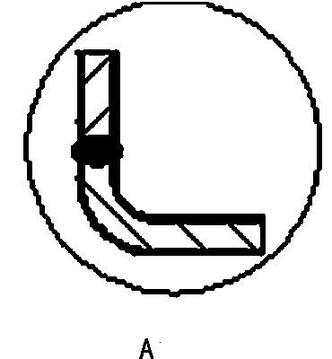
technical field [0001] The invention relates to a bifurcation technology of a large-diameter heat-resistant aluminum alloy pipe, in particular to a method and device for flanging a large-diameter heat-resistant aluminum alloy pipe. Background technique [0002] Large-diameter heat-resistant aluminum alloy tubes are often used as aircraft pipelines. In order to test the flow, temperature and pressure in the aircraft pipeline, it is necessary to divide a fork in the pipeline and install a pipe joint and test sensor to form a T-shaped bifurcation structure. During the operation of the aircraft, the flow, temperature and pressure in the pipeline are detected by sensors. In order to ensure that the welds will not crack due to fatigue after long-term operation, the large-diameter heat-resistant aluminum alloy pipeline bifurcated square structure is set up by flanging technology. The so-called flanging technology refers to the radial opening of the aluminum alloy pipe, and the ope...

Claims


Application Information

Patent Timeline
Patent Type & Authority Applications(China)
IPC IPC(8): B21D39/04
Inventor 李光俊
Owner CHENGDU AIRCRAFT INDUSTRY GROUP
Learn More