Eureka AIR delivers breakthrough ideas for toughest innovation challenges, trusted by R&D personnel around the world.

Energy-saving environment-friendly sintering waste gas waste-heat utilization and pollutant purification process and system

A purification process, energy saving and environmental protection technology, applied in the direction of waste heat treatment, climate sustainability, combustion technology mitigation, etc., can solve the problems of low utilization rate of waste heat from sintering waste gas, no graded utilization of sintering waste gas, and high cost of waste gas purification, so as to improve waste heat Effects of utilization efficiency, emission reduction, and fuel consumption reduction

Inactive Publication Date: 2014-11-05
INST OF PROCESS ENG CHINESE ACAD OF SCI
View PDF6 Cites 26 Cited by
  • Summary
  • Abstract
  • Description
  • Claims
  • Application Information

AI Technical Summary

Problems solved by technology

However, the cost of waste gas purification is high, there is no graded utilization of sintering waste gas, and the utilization rate of waste heat of sintering waste gas is low

Method used


Image

  • Energy-saving environment-friendly sintering waste gas waste-heat utilization and pollutant purification process and system
  • Energy-saving environment-friendly sintering waste gas waste-heat utilization and pollutant purification process and system
  • Energy-saving environment-friendly sintering waste gas waste-heat utilization and pollutant purification process and system

Examples


specific Embodiment

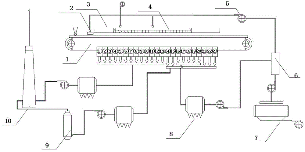
[0055] Such as figure 1 As shown, the flow of hot air is controlled by adjusting the valve of the waste heat pipeline, and the oxygen enrichment level is adjusted so that the sintering waste gas extracted by the bellows is divided into three levels. Counting from the igniter at the head of sintering machine 1, ①- No. bellows is a low-temperature and low-sulfur section, Medium temperature and high sulfur section, It is a high temperature medium sulfur section. Lead out through the pipeline ①- The sintering exhaust gas of the low-temperature and low-sulfur section of the wind box, The sintering waste gas in the medium temperature and high sulfur section of the No. 2 bellows, and the sintering waste gas in the low temperature and low sulfur section are introduced into the dust removal device through the induced draft fan for dust removal. After dust removal, the sulfur content is lower than the national emission standard and is directly discharged into the atmosphere. T...


PUM


Abstract

The invention relates to an energy-saving environment-friendly sintering waste gas waste-heat utilization and pollutant purification process and system. The energy-saving environment-friendly waste gas waste-heat utilization and pollutant purification process includes that sintering waste gas is divided into a low-temperature low-sulfur sintering waste gas, a middle-temperature high-sulfur sintering waste gas and a high-temperature middle-sulfur sintering waste gas according to waste gas temperature and pollutant discharge characteristics; content of sintering waste gas SO2 of the low-temperature low-sulfur is below the national discharge standard, and the SO2 can be directly discharged after dust removal; after the sintering waste gas in a middle-temperature high-sulfur section is subjected to dust removal and desulfurization processing, the SO2 meets the national discharge standard and can be discharged; the sintering waste gas in a high-temperature middle-sulfur section mixed with ring-cold waste gas is led into a sintering machine, and hot-wind igniting and hot-wind sintering are performed. The invention further provides a system for implementing the energy-saving environment-friendly sintering waste gas waste-heat utilization and pollutant purification process. Waste heat of the sintering waste gas can be recycled in classification and gradiently utilized, so that energy can be saved; the low-sulfur waste gas can be discharged directly, so that desulfurization cost of the waste gas is lowered; part of the high-sulfur waste gas participate in circulation, so that total discharge amount of pollutants is decreased, splitting decomposition of dioxin happens due to high temperature, and the purification function of the sintering waste gas is achieved.

Description

technical field [0001] The invention relates to an energy-saving and environment-friendly sintering waste gas waste heat utilization and pollutant purification process and system, in particular to a process and a system for implementing waste heat utilization and pollutant purification treatment by staged treatment of sintering waste gas in iron and steel plants. Background technique [0002] The iron and steel industry is a high-pollution and high-energy-consumption industry. Since iron ore contains a certain amount of sulfur and nitrogen elements, during the sintering process, it will produce sintering waste gas containing a large amount of pollutants such as sulfur dioxide and nitrogen oxides. If it is directly discharged to In the atmosphere, it will cause serious environmental pollution, so it is necessary to purify the pollutants in the sintering waste gas to achieve the effect of environmental protection and emission reduction. [0003] If the carbon in the sinter fue...

Claims


Application Information

Patent Timeline
Patent Type & Authority Applications(China)
IPC IPC(8): F27D17/00F23J15/02F23J15/06
CPCY02E20/30
Inventor 陈运法朱廷钰徐文青黄学静叶猛
Owner INST OF PROCESS ENG CHINESE ACAD OF SCI
Why Eureka
Eureka Blog
Learn More