a centrifugal clutch

A technology for centrifugal clutches and clutch sleeves, applied in the field of clutches, which can solve problems such as high machining accuracy requirements, cumbersome machining, and complex structures, and achieve the effects of low machining accuracy requirements, stable and reliable work, and simple structure

Active Publication Date: 2016-12-07
GUANGZHOU LIANHE TEACHING EQUIP
View PDF5 Cites 0 Cited by
  • Summary
  • Abstract
  • Description
  • Claims
  • Application Information

AI Technical Summary

Problems solved by technology

[0004] At present, most of the existing centrifugal clutches are composed of driving shaft, ratchet, driven parts, pawls, springs, friction blocks and other components. Although this kind of centrifugal clutch can transmit torque well, its structure is relatively complicated. The processing is cumbersome and requires high processing accuracy

Method used


Image

  • a centrifugal clutch
  • a centrifugal clutch
  • a centrifugal clutch

Examples


Embodiment 1

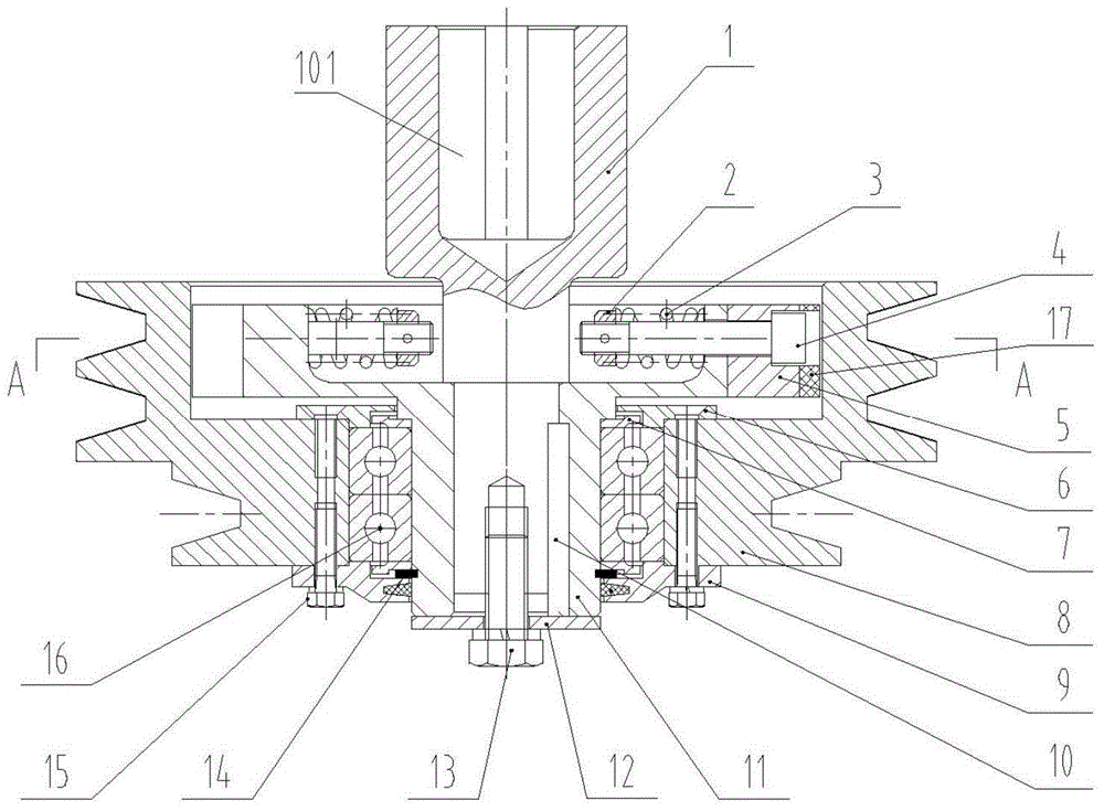
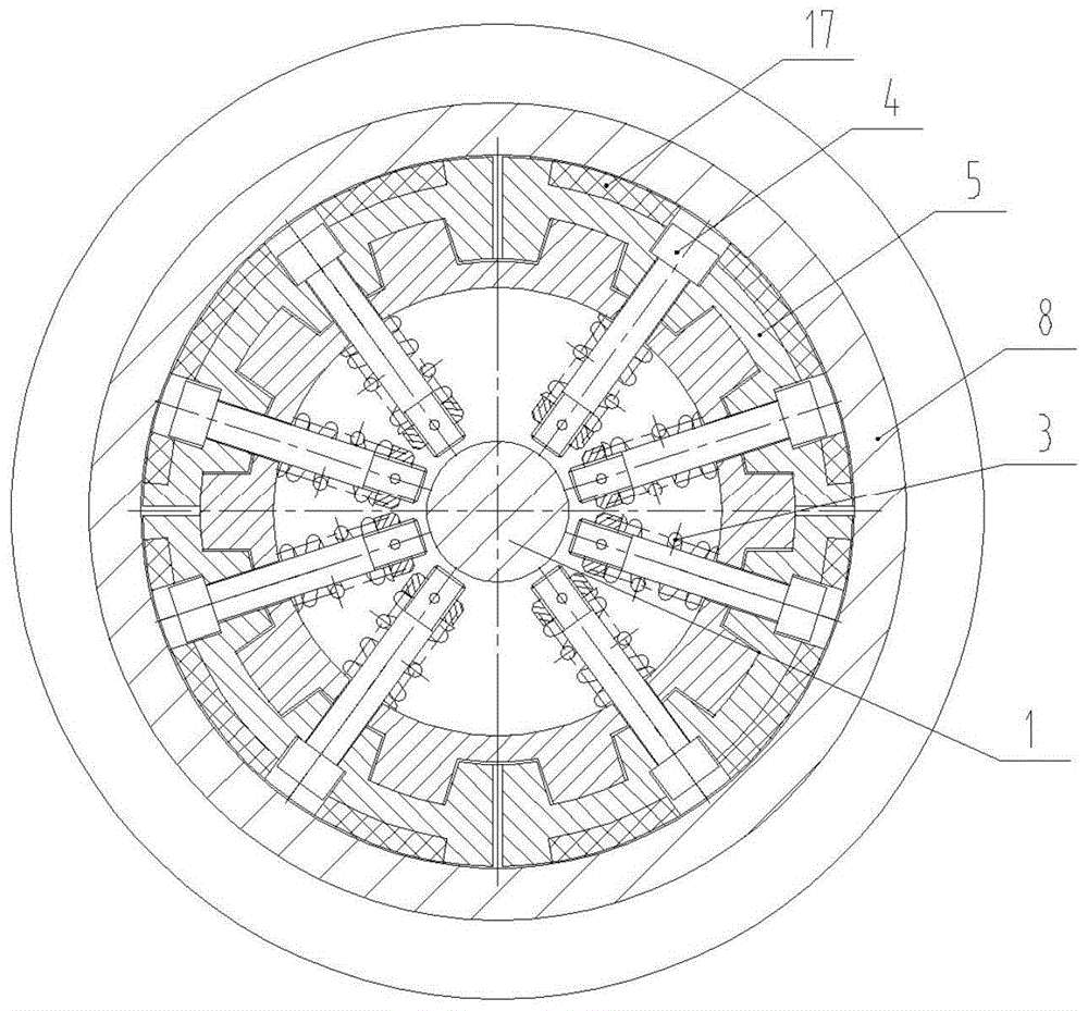
[0023] like figure 1 and figure 2 As shown, a centrifugal clutch involved in the present invention includes a driving part, a centrifugal body and a driven part. The connecting socket 101 is used for connecting the engine. A clutch cover 11 is fitted on the driving shaft 1 and connected with a key 10. The driven member is a pulley 8 and is installed outside the clutch cover 11 through a bearing 16. The centrifugal body is a plurality of brake blocks 5 and is arranged on the clutch Between the sleeve 11 and the inner hole of the pulley 8, as a non-limiting preference, there are four brake blocks 5 . Each brake block 5 is respectively engaged with the clutch sleeve 11 through splines, so as to improve the reliability of transmission. Friction plates 17 are inlaid on the outer wall of each brake block 5 to increase the friction between the brake block 5 and the pulley 8 and improve the reliability of transmission.

[0024] Elastic connecting components are respectively provi...

Embodiment 2

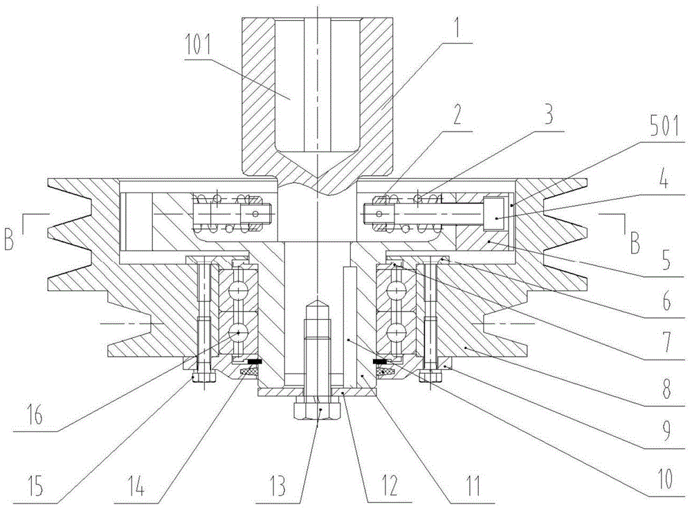
[0029] like image 3 and Figure 4 As shown, a centrifugal clutch involved in the present invention includes a driving part, a centrifugal body and a driven part. The connecting socket 101 is used for connecting the engine. A clutch sleeve 11 is set on the driving shaft 1 and connected by a key. The driven member is a pulley 8 and is installed outside the clutch sleeve 11 through a bearing 16. The centrifugal body is a plurality of brake blocks 5 and is arranged on the clutch sleeve. Between 11 and the inner hole of the pulley 8, as a non-limiting preference, there are four brake blocks 5 . Each brake block 5 is respectively engaged with the clutch sleeve 11 through splines, so as to improve the reliability of transmission. The outer wall of each brake block 5 is processed with straight-toothed small teeth 501 to increase the friction between the brake block 5 and the pulley 8 and improve the reliability of transmission.

[0030] Other structures of this embodiment are the...


PUM


Abstract

The invention discloses a centrifugal clutch, which comprises a driving part, a centrifugal body and a driven part. The pulley is installed on the outside of the clutch sleeve through bearings. The centrifugal body is a plurality of brake blocks and is arranged between the clutch sleeve and the inner hole of the pulley. An elastic connection assembly is respectively provided between each brake block and the clutch sleeve. The brake block is in close contact with the clutch sleeve under the action of the elastic connection component, and when the centrifugal force of the brake block is large enough, it can overcome the restraint of the elastic connection component and drive the pulley to rotate. The beneficial effects of the invention are: simple structure, easy processing, low requirements on processing accuracy, stable and reliable operation, and fast clutching and disengagement can be realized through engine speed control.

Description

technical field [0001] The invention relates to a clutch, in particular to a centrifugal clutch. Background technique [0002] Centrifugal clutch transmits torque through friction, and its basic structure consists of three elements: driving part, centrifugal body and driven part. The centrifuge is slipped on the driving part, and the engine drives the driving part to rotate and accelerate to throw it out in the radial direction. When the driving part reaches the specified angular velocity, the thrown centrifugal body is pressed against the inner wall of the driven part, and the friction force forces it out. Into a state of motion to transmit torque, the driven part of the clutch can be connected to the load directly or through a mechanism such as a pulley. [0003] Due to the simple structure and compact size of the centrifugal clutch, its combination or separation can be controlled by controlling the speed of the engine, without a special operating mechanism, and it can au...

Claims


Application Information

Patent Timeline
Patent Type & Authority Patents(China)
IPC IPC(8): F16D43/18
Inventor 景丽
Owner GUANGZHOU LIANHE TEACHING EQUIP
Why Eureka
Try Eureka