Oil-water well stratigraphic reservoir water-injection decontamination filtering self-cleaning device

A filter device and self-cleaning technology, which is applied in the direction of sterilization/microdynamic water/sewage treatment, wellbore/well components, production fluid, etc. wall corrosion and other problems, to achieve the effect of improving the water quality of injection water, solving the costs related to the amount of shutdown maintenance and cleaning engineering, and solving the environmental protection problems of secondary pollution

Inactive Publication Date: 2014-11-05
陆威延
View PDF1 Cites 7 Cited by
  • Summary
  • Abstract
  • Description
  • Claims
  • Application Information

AI Technical Summary

Problems solved by technology

[0002] With the increasing amount of oil produced in the formation, water injection is also the most widely used oil recovery method in oil fields. Water injection must be used to supplement formation energy to improve oil displacement efficiency and stabilize oil well production capacity. After the treated water is transported to the wellhead for injection, there will be a large number of bacteria, especially sulfate reducing bacteria (SRB). The reaction product S2- will combine with Fe2+ produced by various corrosion factors to form FeS, and the suspended solids will increase significantly. Injected water containing a small amount of sulfide and other insoluble substances will not only cause corrosion on the pipe wall, but also produce dirt or sludge containing ferrous sulfide on the pipe wall. These solid particles, mechanical impurities, dirt, etc. are directly injected into the oil layer, causing Pores in the oil layer are clogged, and the energy of the oil reservoir in the formation is not fully replenished, which seriously affects the production and development of the oil field.
The existing filter cannot realize timely self-cleaning function

Method used


Image

  • Oil-water well stratigraphic reservoir water-injection decontamination filtering self-cleaning device
  • Oil-water well stratigraphic reservoir water-injection decontamination filtering self-cleaning device

Examples


Embodiment Construction

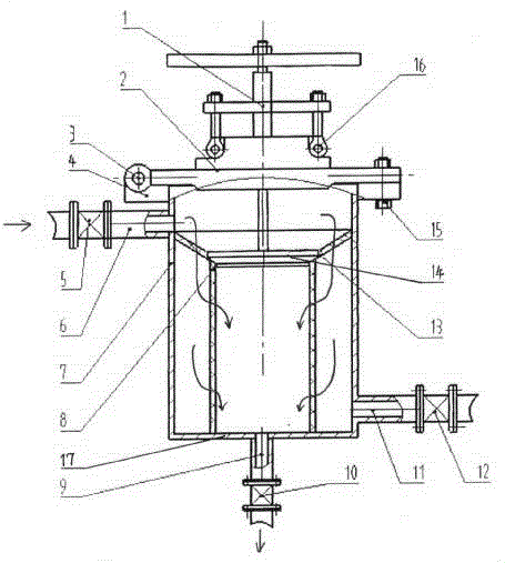
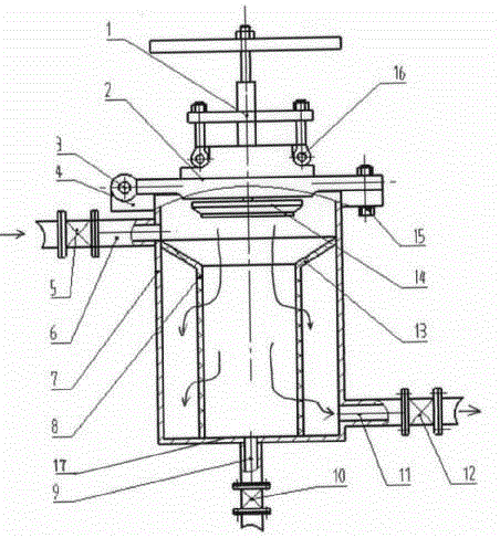
[0009] Detailed description in conjunction with the drawings: As shown in the figure, the actuator 1 is connected to the upper flange bonnet 2 through bolts 16, and one side of the upper flange bonnet 2 is connected to the shell cylinder flange 4 through a pin shaft 3, and the upper flange The bonnet 2 is connected to the flange 4 of the shell cylinder through uniformly distributed bolts 15. The shell cylinder 7 is respectively provided with a water inlet pipe 6 with a water inlet valve 5 on the upper part of the side wall, and a water inlet pipe 6 with a water outlet valve 12 on the lower part of the side wall. The water outlet pipe 11, the sewage outlet pipe 9 with the sewage valve 10 at the head end, the valve stem end of the actuator 1 is connected to the sealing plug 14, the outer shell cylinder 7 is equipped with a copper powder particle sintered filter screen inner cylinder 8, and the inner cylinder The large-diameter end of the bell mouth filter screen cone surface 13 o...


PUM


Abstract

The invention relates to an oil-water well stratigraphic reservoir water-injection decontamination filtering self-cleaning device. With the device, an execution mechanism can be operated such that back-wash self-cleaning can be performed. The device comprises an upper flange valve cover with the execution mechanism, and a housing cylinder body with a flange on the upper part and a sealing head on the lower part. An inner cylinder body with a Trumpet-opening copper-powder-particle-sintered filtering sieve on the upper part is arranged inside the housing cylinder body. The housing cylinder body is respectively provided with a water inlet pipe with a valve, a water outlet pipe with a valve, and a sewage discharge pipe with a valve. During a normal operation process, the execution mechanism valve rod seal is elevated; inlet water flows through the inner cylinder body with the copper powder particle sintered filtering sieve, and impurities are retained on the tapered surface of the trumpet opening, such that purposes of filtering and sterilizing are achieved. During a self-cleaning process, the execution mechanism valve rod seal is sealed with a sealing groove of the inner cylinder body; water flows through the trumpet opening tapered surface, and back-washes the wall surface of the inner cylinder body; and a sewage-discharge valve is opened, such that sewage-discharge back-wash is carried out. With the device provided by the invention, sterilization, filtration and back-wash self-cleaning can be realized with simple operations; and an oil-water well stratigraphic reservoir water-injection decontamination filtering problem can be effectively solved.

Description

technical field [0001] The invention relates to a water injection decontamination filter self-cleaning device for an oil-water well stratum reservoir. Especially the decontamination filter device that can operate the actuator for backwashing and self-cleaning. Background technique [0002] With the increasing amount of oil produced in the formation, water injection is also the most widely used oil recovery method in oil fields. Water injection must be used to supplement formation energy to improve oil displacement efficiency and stabilize oil well production capacity. After the treated water is transported to the wellhead for injection, there will be a large number of bacteria, especially sulfate reducing bacteria (SRB). The reaction product S2- will combine with Fe2+ produced by various corrosion factors to form FeS, and the suspended solids will increase significantly. Injected water containing a small amount of sulfide and other insoluble substances will not only cause c...

Claims


Application Information

Patent Timeline
Patent Type & Authority Applications(China)
IPC IPC(8): C02F1/50E21B43/20
Inventor 陆威延张月迟丽薇刘渊龚丽杨晓云陆东升
Owner 陆威延
Why Eureka
Try Eureka