An on-load voltage regulating and capacity regulating transformer

A technology for transformers and transformer shells, applied in transformers, variable transformers, variable inductors, etc., can solve the problems of polluting arc-extinguishing medium transformer oil, degradation of transformer oil insulation performance, and endangering the service life of transformers. Reliable arc performance, long service life, and the effect of eliminating residual magnetism

Active Publication Date: 2016-10-05
巨元智能电气(浙江)有限公司
View PDF6 Cites 0 Cited by
  • Summary
  • Abstract
  • Description
  • Claims
  • Application Information

AI Technical Summary

Problems solved by technology

Before the present invention was made, the problems existing in this type of on-load capacity-adjusting voltage-regulating transformer were: 1. During the process of capacity-adjusting and voltage-regulating, the electric arc generated by the switching of the moving and static contacts would pollute the arc-extinguishing medium transformer oil, causing the transformer The insulation performance of the oil decreases rapidly, which seriously endangers the service life of the transformer and poses a great safety hazard
2. When the capacity is switched, all the contacts of the high and low voltage groups are switched synchronously, and the arc is greatly affected by the high current of the low voltage side winding, which makes the dynamic and static contacts easily burned

Method used


Image

  • An on-load voltage regulating and capacity regulating transformer
  • An on-load voltage regulating and capacity regulating transformer
  • An on-load voltage regulating and capacity regulating transformer

Examples


Embodiment Construction

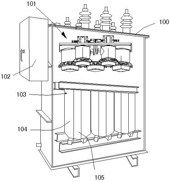
[0021] see figure 1 . The automatic controller 102 is installed on the upper left outer wall of the transformer housing 100, and the tap changer 101, high voltage winding 103, low voltage winding 104 and winding core 105 are placed in the inner cavity of the transformer housing 100 and immersed in transformer oil.

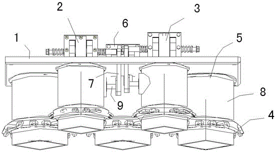
[0022] see figure 2 . The mounting plate 1 is horizontally and fixedly placed on the upper part of the inner cavity of the transformer, and its top surface is used to fix the operating parts, namely: the capacity adjustment operation mechanism 6, the first voltage adjustment operation mechanism 2 and the second voltage adjustment operation mechanism 3, these three The composition and structure of the mechanism are exactly the same, with a set of independent bistable permanent magnet assembly and its toggle rod 7 respectively. The coil in the bistable permanent magnet assembly is connected to the output end of the automatic controller on the transformer. The upp...


PUM


Abstract

An on-load voltage regulating and capacity regulating transformer, including tap changer and other components, the tap changer is composed of three sets of operating mechanisms, three capacity regulating switches and two voltage regulating switches, and each operating mechanism has a set of bistable permanent magnets The component and its toggle rod, and the switch each include a vacuum-sealed insulating cylinder. The switching surfaces of the moving contact piece and the static contact piece are located in the vacuum cylinder cavity of the insulating cylinder; the high-voltage side static contact of the three capacity adjustment switches The width of the switching face of the slice is smaller than that of the low voltage side. Since the switching surface of the dynamic and static contacts is located in the vacuum cylinder cavity, the present invention has the advantages of reliable arc extinguishing performance, long service life and transformer oil will not be polluted by arcs; moreover, the high-voltage winding is cut off first, and then the low-voltage winding is cut off. After the low-voltage winding is connected first, and then the high-voltage winding is connected, the arc is small, which is beneficial to eliminate the residual magnetism in the transformer core, avoids the inrush current and overvoltage when the high-voltage side winding is connected again, and effectively reduces the voltage fluctuation amplitude during the switching process value purpose.

Description

technical field [0001] The invention relates to an on-load voltage regulating and capacity regulating transformer. Background technique [0002] The structure of the existing capacity-regulating and voltage-regulating transformer usually includes a transformer housing, a high-voltage and low-voltage coil, an automatic controller, and structural components such as a tap switch composed of an operating mechanism, a capacity-regulating switch and a voltage-regulating switch. There is a type of on-load capacity regulating transformer, the transformer shell is filled with oil, and the tap changer and coil are immersed in the transformer oil. During operation, when the automatic controller connected to the bistable permanent magnet component of the tap changer receives an electrical signal related to capacity and voltage regulation, the output circuit of its execution module is triggered, so that the correspondingly connected capacity and voltage regulation switch starts The acti...

Claims


Application Information

Patent Timeline
Patent Type & Authority Patents(China)
IPC IPC(8): H01F29/04H01F27/40H01H1/56H01H3/32
Inventor 傅建平林秋红姜福照王志文周海波
Owner 巨元智能电气(浙江)有限公司
Why Eureka
Try Eureka