Totally-worry-free lightning arrester

A lightning arrester and lightning arrester technology, applied in the field of lightning arresters, can solve problems such as thermal collapse and aging of zinc oxide arresters

Pending Publication Date: 2022-03-15
无锡市同腾复合材料有限公司
View PDF1 Cites 0 Cited by
  • Summary
  • Abstract
  • Description
  • Claims
  • Application Information

AI Technical Summary

Problems solved by technology

[0004] In the prior art, the ability of zinc oxide surge arrester valves to withstand power frequency voltage is closely related to the duration of action. Long-term exposure to high frequency power frequency voltage can easily cause problems such as thermal collapse and aging of zinc oxide surge arresters.

Method used


Image

  • Totally-worry-free lightning arrester
  • Totally-worry-free lightning arrester
  • Totally-worry-free lightning arrester

Examples


Embodiment 1

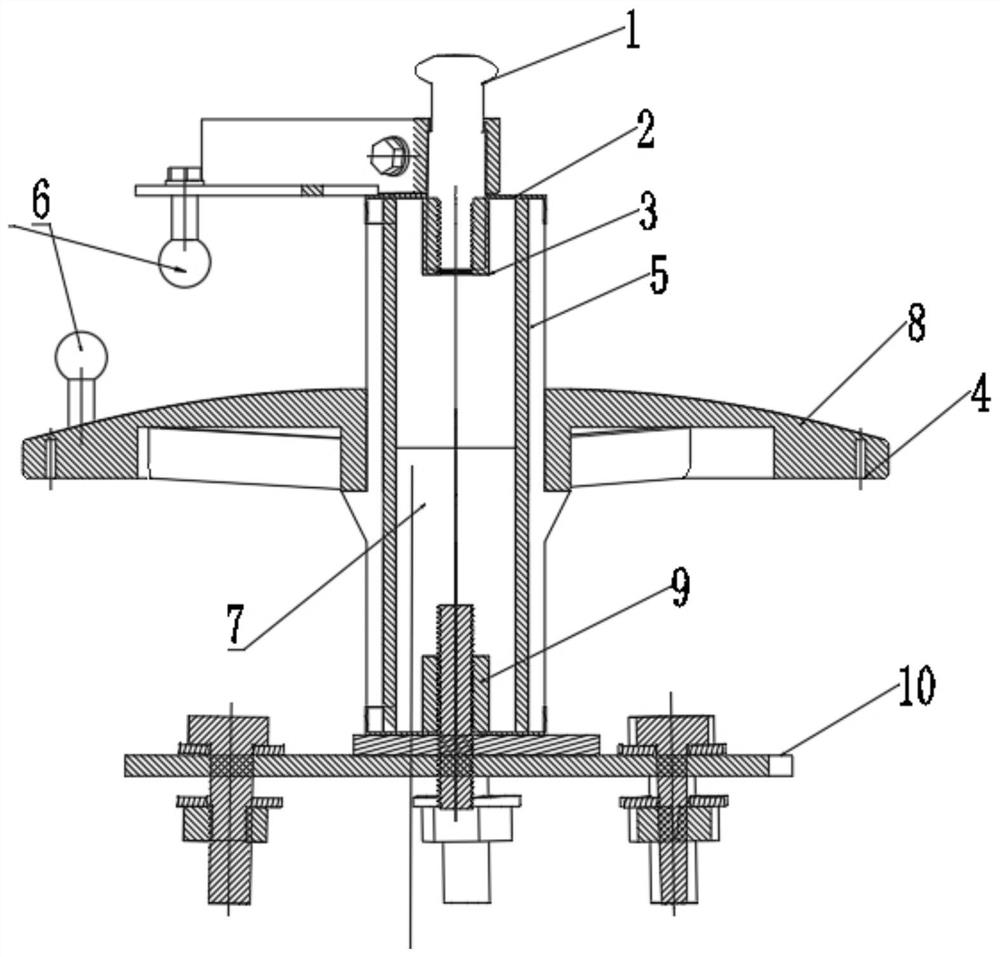
[0031] see figure 1 and 3 As shown, the worry-free lightning protection device includes 10kV worry-free surge arrester, and the 10kV worry-free surge arrester includes upper terminal 1, upper sealant 2, aluminum terminal seat 3, multi-cavity system 4, heat-shrinkable sealing tube 5, electrodes 6. Zinc oxide valve piece 7, synthetic sheath 8, lower terminal block 9, base 10; a single zinc oxide valve piece 7 is arranged in the heat-shrinkable sealing tube 5, and the top of the zinc oxide valve piece 7 passes through the aluminum terminal base 3 and the The upper terminal 1 is connected, and the upper sealant 2 is provided at the connection between the upper terminal 1 and the heat-shrinkable sealing tube 5. A connecting plate is installed on the connecting terminal 1, an electrode 6 is installed on the end of the connecting plate away from the upper connecting terminal, the bottom end of the zinc oxide valve plate 7 is connected with the lower connecting terminal 9, and the bo...

Embodiment 2

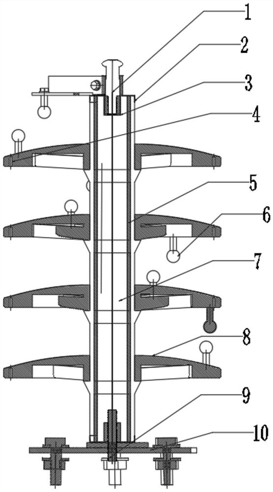
[0035] see figure 2 As shown, the 35kV worry-free lightning protection device is different from the 10kV worry-free lightning protection device in that: the heat-shrinkable sealing tube 5 of the surge arrester containing multiple sets of zinc oxide valve plates 7 is provided with a plurality of zinc oxide at equal intervals The valve plate 7, the outer wall of the heat-shrinkable sealing tube 5 of the surge arrester of multiple groups of zinc oxide valve plates 7 is provided with a plurality of synthetic sheaths 8, and the synthetic sheaths 8 at both ends are provided with a single electrode 6, and the multiple electrodes 6 in the middle A synthetic sheath 8 is provided with two electrodes 6, and the two electrodes 6 are respectively located on the upper and lower sides of the synthetic sheath 8;

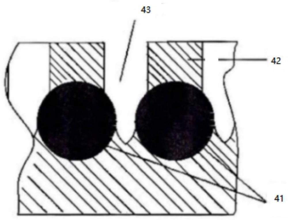
[0036]Both the lightning arresters of Embodiment 1 and Embodiment 2 have two ways of lightning discharge. One is a multi-cavity system using "Simple Arc Quenching Technology". As...


PUM


Abstract

The invention discloses a full-worry-free lightning arrester which comprises a vertical discharge system and a multi-cavity system, the vertical discharge system is arranged on a synthetic sheath of a lightning arrester, electrodes comprise an upper electrode and a lower electrode, the upper electrode and the lower electrode are arranged at intervals in the axial direction of the lightning arrester, the upper electrode is located above the lower electrode, and the multi-cavity system is located above the lower electrode. A discharge gap is formed between the upper electrode and the lower electrode; a multi-cavity system is annularly arranged on the synthetic sheath of the lightning arrester; a plurality of spherical electrodes are arranged along the side wall of the synthetic sheath in an annular array, an arc extinguish chamber is arranged at the position of every two adjacent spherical electrodes, the arc extinguish chambers are located on the synthetic sheath, each arc extinguish chamber is a cavity with a single opening, and the opening of each arc extinguish chamber is an arc nozzle; the lightning arrester has the advantages of being simple in structure, good in protection performance, not prone to being affected with damp and aging elements and the like. The device does not depend on the size of the grounding resistance of a product, so that the device has no special requirement on the grounding resistance of a tower, is convenient to install especially for lines in mountainous areas, and saves the grounding cost.

Description

technical field [0001] The invention belongs to the technical field of lightning arresters, in particular to a worry-free lightning protection device. Background technique [0002] The arrester is an electrical appliance used to protect electrical equipment from high transient overvoltage hazards and limit the freewheeling time and often limit the freewheeling value. Its main material is zinc oxide. The arrester is usually connected between the grid wire and the ground wire, and sometimes it is also connected next to the electrical winding or between the wires. [0003] Chinese patent CN212874187U discloses a series-gap metal zinc oxide arrester, which includes a arrester body, on the outer wall of the arrester body, electrical equipment connected to the wire is installed through a drain ring, and the bottom end of the electrical equipment is connected to the arrester body through an insulator bracket. The clamping ring and grounding protection, the outer wall of the clamp...

Claims


Application Information

Patent Timeline
Patent Type & Authority Applications(China)
IPC IPC(8): H01T1/02H01T4/16
CPCH01T1/02H01T4/16
Inventor 柳力吴欣洋王瑞珏肖孟金花媛
Owner 无锡市同腾复合材料有限公司
Why Eureka
Try Eureka