
Laser hybrid light source projector and light source device thereof

A technology of a light source device and a mixed light source, applied in the field of projection display, can solve the problems such as the innate advantage of the solid light source in nanosecond high-speed response, the performance degradation of the projector, and the deviation of the color wheel rotation speed, so as to eliminate the influence of the aperture effect and improve the The effect of image quality and brightness enhancement

Inactive Publication Date: 2014-10-29
HANGZHOU JIN LI OPTOELECTRONICS TECH +1
View PDF5 Cites 20 Cited by
  • Summary
  • Abstract
  • Description
  • Claims
  • Application Information

AI Technical Summary

Problems solved by technology

[0005] The shortcomings of using the color wheel are mainly reflected in: due to the use of a rotating mechanical color wheel, the response speed of the entire light source system is greatly reduced, and the inherent advantages of the nanosecond-level high-speed response of the solid light source are not exerted; the speed of the color wheel is limited. Very slight deviation will cause color distortion and image quality deterioration; the color wheel coated with phosphor, the turntable is all exposed to the air, after a period of operation, the color wheel will be dirty, the performance of the projector will decline, and cleaning and maintenance are required

Method used


Image

  • Laser hybrid light source projector and light source device thereof
  • Laser hybrid light source projector and light source device thereof

Examples


Embodiment Construction

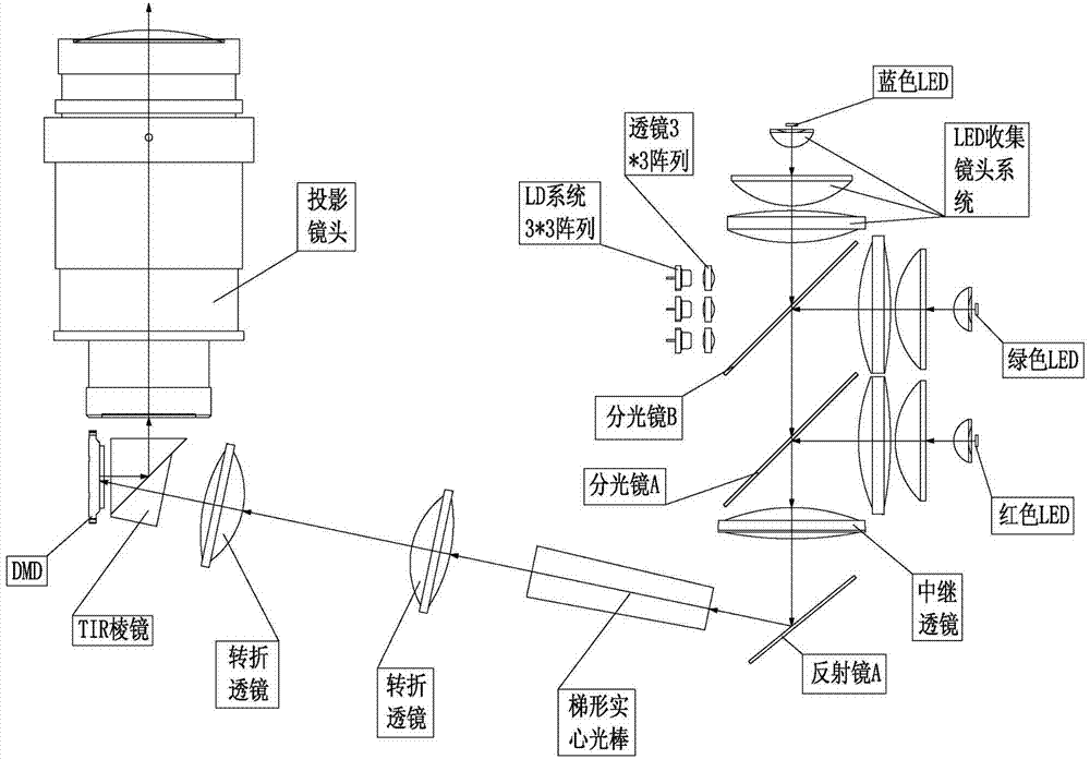
[0021] Such as figure 2 As shown, the light source device of the laser mixed light source projector of the present invention includes a blue LED light source, a red LED light source, a green LED light source (blue LED chip, coated with green fluorescent powder on the surface) and a lens group located at the front end of each light source (i.e. LED collection lens system), blue semiconductor laser tube (i.e. LD system) and its front-end lens group, beam splitter A (reflects red light, transmits green light and blue light), and beam splitter B (reflects green light, transmits Blu-ray). The green LED light source is opposite to the semiconductor laser tube, the beam splitter B is located between the two, the blue LED light source is arranged on the side of the beam splitter B, and the beam splitter A is arranged in front of the red LED light source.

[0022] The blue light emitted by the blue LED light source passes through the beam splitter B and the beam splitter A; the r...


PUM


Abstract

The invention relates to a laser hybrid light source projector and a light source device thereof. The light source device comprises a blue LED light source, a red LED light source, a green LED light source, lens groups at the front ends of the light sources, a blue semiconductor laser tube, a lens group at the front end of the blue semiconductor laser tube, a spectroscope A and a spectroscope B; the surface of the green LED light source is provided with green fluorescent powder; the green LED light source is opposite to the semiconductor laser tube, the spectroscope B is located between the green LED light source and the semiconductor laser tube, the blue LED light source is arranged at one side of the spectroscope B, and the spectroscope A is arranged at the front of the red LED light source. The laser hybrid light source projector does not use the light source system of a laser projector with a color wheel, so that the influence of the color wheel on the picture quality is avoided; the blue semiconductor laser irradiates the fluorescent powder on the green LED, the brightness of the original green LED is obviously improved without increasing the numerical aperture of the light emitting area of the LED, and accordingly the output brightness of the projector is improved.

Description

[0001] technical field [0002] The invention belongs to the technical field of projection display, and in particular relates to a laser mixed light source projector and a light source device thereof. Background technique [0003] Laser mixed light source means that the light source of the projector is composed of LED and LD (Laser Diode, semiconductor laser). At present, the laser hybrid / pure laser light source (R+B) projector, see the principle scheme figure 1 : The red LED (or red LD) and the blue LD excite the green phosphor on the color wheel to generate green light, the blue LD emits light directly, and alternately irradiates the DMD (Digital Micro mirror Device) in time, using the visual residue of the human eye effect, a color image is presented on the screen through a projection lens. [0004] On the color wheel, about 1 / 5 to 1 / 4 of the circumference area is a piece of transparent glass, and the remaining area of ​​about 3 / 4 to 4 / 5 is a metal plate as thick as gla...

Claims


Application Information

Patent Timeline
Patent Type & Authority Applications(China)
IPC IPC(8): G03B21/20
Inventor 聂瑾禄陈灵
Owner HANGZHOU JIN LI OPTOELECTRONICS TECH
Learn More