Apparatus for rapidly gasifying liquid nitrogen through circulating water bath, and operating method thereof

A technology of circulating water bath and gasification device, which is applied in the method of container discharge, fixed-capacity gas storage tank, gas/liquid distribution and storage, etc. It can reduce investment costs, eliminate pressure fluctuations, and improve security capabilities.

Active Publication Date: 2014-10-29
CHINA PETROLEUM & CHEM CORP
View PDF8 Cites 5 Cited by
  • Summary
  • Abstract
  • Description
  • Claims
  • Application Information

AI Technical Summary

Problems solved by technology

The steam water bath liquid nitrogen gasification system has a complicated process and cumbersome operation. It needs to pre-cool the liquid pump, boil the water pump, and pass the steam. It usually takes more than 30 minutes, especially in the cold winter climate in northern China. It is more difficult to start. There is a problem of freezing blockage in the water system and steam system, and it cannot provide emergency nitrogen supply. However, the equipment has a compact structure and a small footprint. Once it is put into use, it can run stably for a long time
The air bath liquid nitrogen gasification system has a simple process and relatively simple operation, but the equipment is bulky, and the operation of the equipment is affected by rainy weather or winter rain and snow in northern China.
The existing steam water bath liquid nitrogen gasification system consumes a lot of steam and electric energy; the process is relatively complicated, the operation is cumbersome, and it is more restricted by external conditions; the start-up time is relatively long
The existing air bath liquid nitrogen gasification process is greatly affected by the regional climate

Method used


Image

  • Apparatus for rapidly gasifying liquid nitrogen through circulating water bath, and operating method thereof
  • Apparatus for rapidly gasifying liquid nitrogen through circulating water bath, and operating method thereof
  • Apparatus for rapidly gasifying liquid nitrogen through circulating water bath, and operating method thereof

Examples


Embodiment Construction

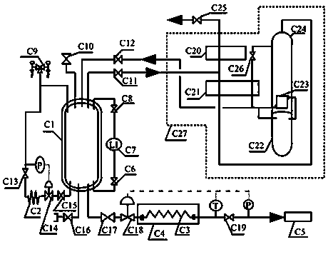
[0042] The following takes an external supply of 20,000 cubic meters of nitrogen per hour, and the normal pressure of the nitrogen pipe network is 0.5 MPa as an example to illustrate the rapid gasification device for liquid nitrogen in a circulating water bath. Select the pressure-resistant low-temperature liquid nitrogen vacuum tank with a pressure rating of 1.0 MPa and an effective volume of 50 cubic meters, and install the equipment according to image 3 The process shown is installed in place. Assuming that the production of the full low-pressure air separation unit is normal, all the valves of the circulating water bath liquid nitrogen quick gasification device outside the cold box C27 are closed, and then proceed as follows:

[0043] 1. Open the liquid level gauge, pressure gauge, and valve in front of the safety explosion-proof membrane of liquid nitrogen tank C1;

[0044] 2. Open the C11 and C12 valves, and fill the liquid in C1 to above 80% of the liquid level;

[0...


PUM


Abstract

The invention provides an apparatus for rapidly gasifying liquid nitrogen through circulating water bath, and an operating method thereof. The apparatus comprises a pressure cryogenic liquid tank C1, a boost gasifier C2, a circulating water bath liquid nitrogen gasifier C3, a water cooling tower circulating water collecting pool C4 and a control valve C18; the bottom of the pressure cryogenic liquid tank C1 is connected with the circulating water bath liquid nitrogen gasifier C3 through the control valveC18, liquid nitrogen from the pressure cryogenic liquid tank C1 is heated by flowing circulating water and gasifies, the gasified liquid nitrogen enters a nitrogen pipe network system C5, and the flowing circulating water is from the water cooling tower circulating water collecting pool C4. The apparatus can realize the emergent rapid demands of a nitrogen system, can complete preset operation within 1-2min, gasifies liquid nitrogen to form nitrogen, and sends nitrogen to the nitrogen pipe network, and the liquid tank with a proper volume is selected according to production process requirements to maintain a liquid nitrogen emergency gasifying device within a certain time in order to win precious time to deal with unexpected accidents.

Description

technical field [0001] The invention belongs to the technical field of separation of oxygen and nitrogen from cryogenic liquefied air in industrial production, gasification of liquid nitrogen and compression transportation, and in particular relates to a circulating water bath liquid nitrogen rapid gasification device and an operation method. Background technique [0002] In large-scale industrial production, there are generally supporting scale air separation units, and the separated nitrogen is transported to the pipe network through compression, which is used by each production unit as emergency replacement of equipment containers, sealing and isolation, and conveying materials. The continuous and stable supply of nitrogen Very important. However, in the long-term production, due to the constraints of certain conditions, it is inevitable that the abnormal operation of the air separation unit needs to be reduced, the nitrogen compressor suddenly stops in chains, and the ex...

Claims


Application Information

Patent Timeline
IPC IPC(8): F17C7/04
Inventor 常兴路
Owner CHINA PETROLEUM & CHEM CORP
Why Eureka
Try Eureka