Parking mechanism for vehicle

A parking mechanism and vehicle technology, applied in vehicle parts, mechanical equipment, braking components, etc., can solve problems such as complex structure, achieve the effects of reducing weight, improving space efficiency, and preventing tipping

Active Publication Date: 2014-10-29
HONDA MOTOR CO LTD
View PDF6 Cites 5 Cited by
  • Summary
  • Abstract
  • Description
  • Claims
  • Application Information

AI Technical Summary

Problems solved by technology

[0005] As described above, in the parking mechanism described in Patent Document 1, the plate supporting the rotation shaft of the parking lever is fastened to the transmission case with the first bolt and the second bolt, so that the structure is complicated and the bolts are complicated. There is a need to improve the structure in terms of space efficiency improvement, small size and weight reduction, and cost reduction, such as increased bolt holes.

Method used


Image

  • Parking mechanism for vehicle
  • Parking mechanism for vehicle
  • Parking mechanism for vehicle

Examples


Embodiment

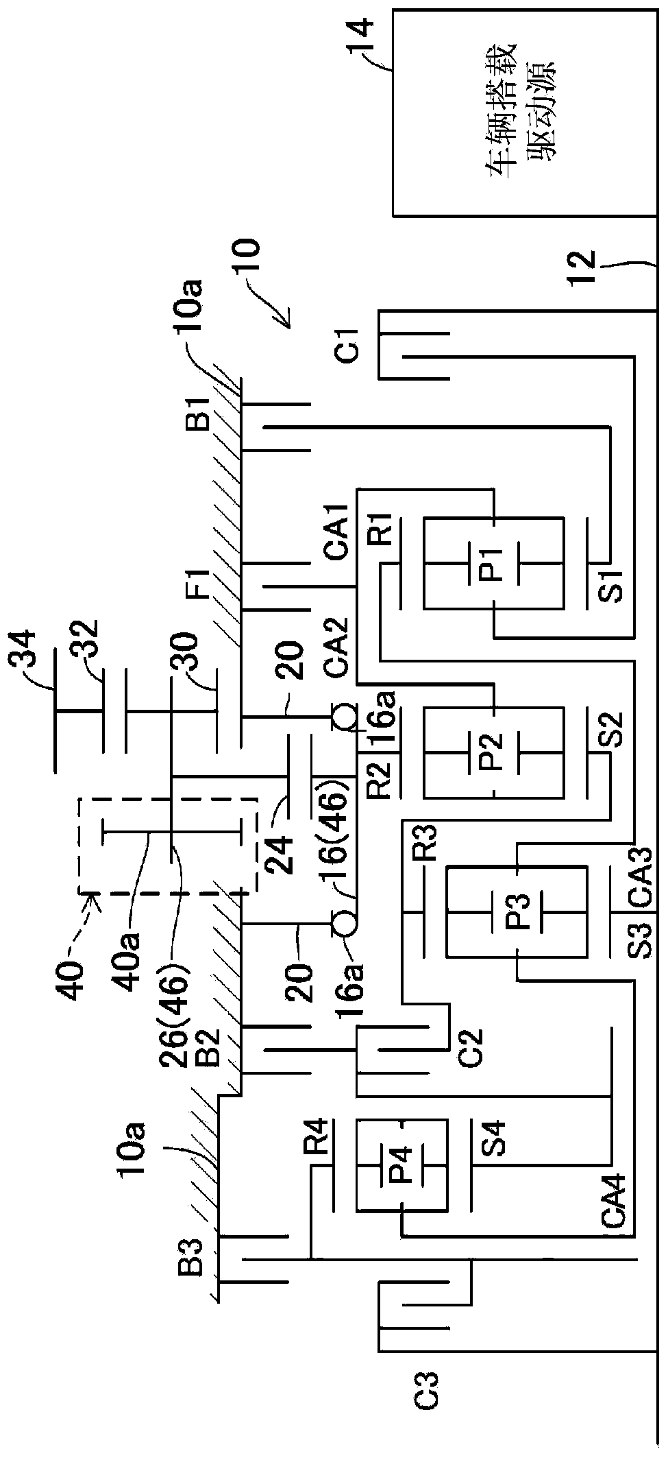
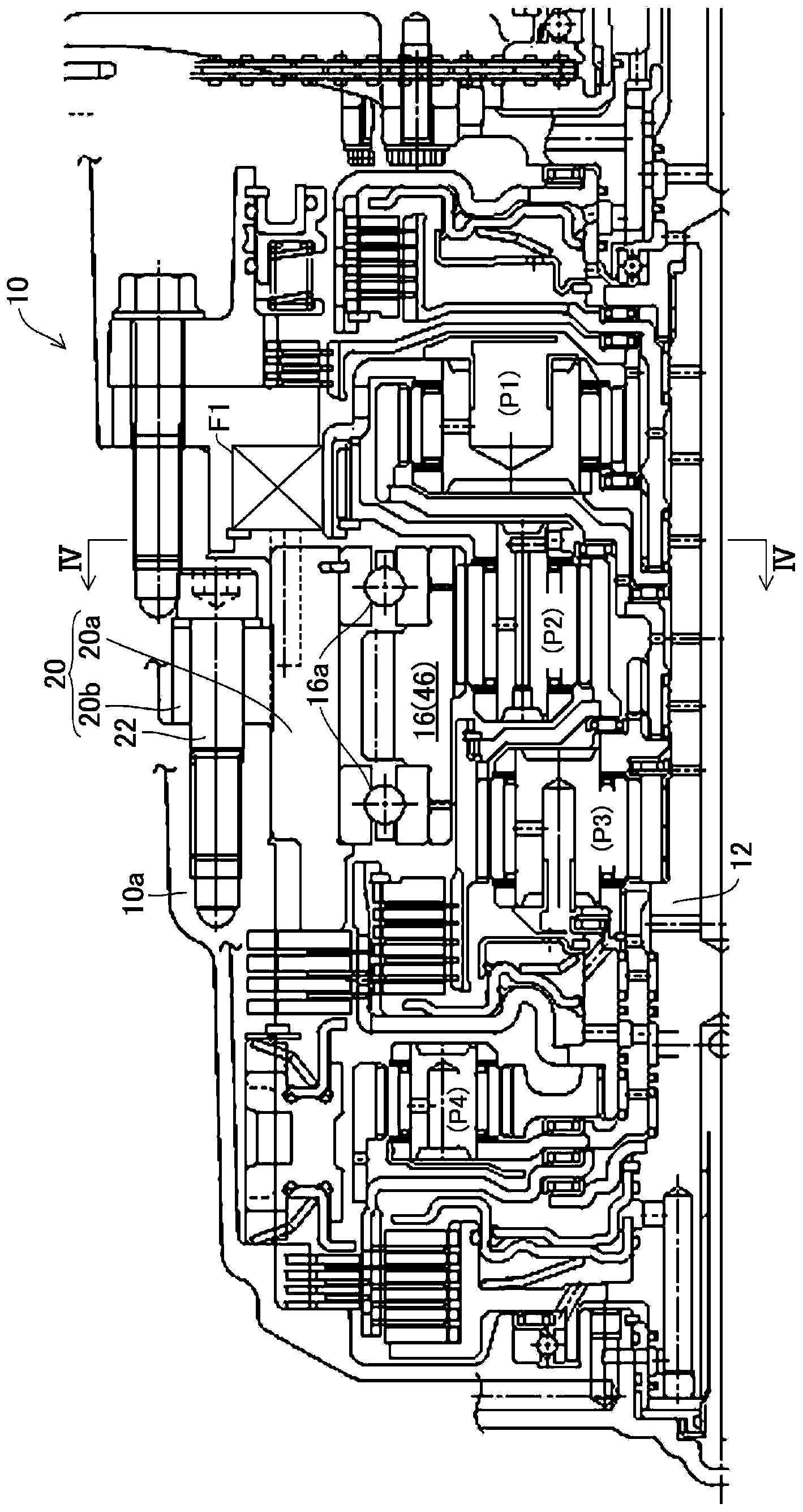
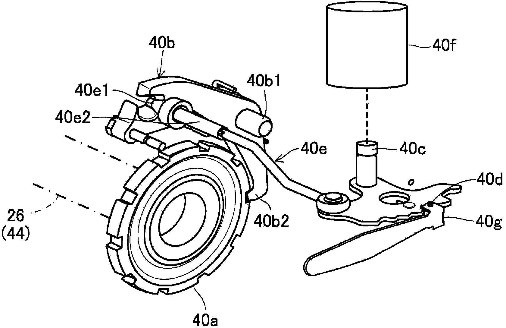
[0019] figure 1 It is a skeleton diagram showing the structure of the upper half centering on the input shaft of the automatic transmission provided with the vehicle parking mechanism of the embodiment, figure 2 yes figure 1 A longitudinal sectional view of the automatic transmission shown, image 3 yes figure 1 An explanatory diagram of the parking mechanism shown, Figure 4 is schematically shown from figure 2 A cross-sectional view of the overall structure of the automatic transmission viewed from the line IV-IV of Figure 5 yes Figure 4 An explanatory diagram of the support components shown.

[0020] exist figure 1 10 indicates an automatic transmission. The automatic transmission 10 is composed of a planetary gear type transmission having 10 forward speeds and 1 reverse speed. The automatic transmission 10 is accommodated in a transmission case 10a.

[0021] In the automatic transmission 10 , the input shaft 12 is connected to a vehicle-mounted drive source (an...


PUM


Abstract

A parking mechanism for a vehicle includes an automatic transmission, a parking gear, a parking pawl, and a parking-pawl turn member. The parking gear is fixed to a part formed by any of an output shaft of the automatic transmission and an intermediate member connected to the output shaft. The parking pawl is turnably attached to a turn shaft that is supported by a plate fastened to a transmission case by a first bolt and a second bolt. The parking-pawl turn member turns the parking pawl into engagement with the parking gear. An extending part formed by extending a support member that turnably supports the part of the automatic transmission is substituted for the plate. The extending part is fastened to the transmission case by the first bolt.

Description

technical field [0001] The invention relates to a parking mechanism of a vehicle. Background technique [0002] As a parking mechanism for a vehicle, the following mechanism is proposed in Patent Document 1, which includes the following parts: a parking gear fixed to an output member of an automatic transmission; a parking lever swingably fixed to a rotary shaft, The rotation shaft is supported by a plate, and the plate is fastened to the transmission case by first and second bolts; and a parking lever swing member swings the parking lever to lock the parking gear freely. [0003] More specifically, the parking lever is fixed to the rotating shaft in a swingable manner, and the rotating shaft is supported by a plate fastened to the transmission case by the first bolt and the second bolt, and the plate is triangular in side view. The lever is configured to engage and lock the parking gear. [0004] Patent Document 1: Japanese Patent Laid-Open No. 2004-44689 [0005] As des...

Claims


Application Information

Patent Timeline
Patent Type & Authority Applications(China)
IPC IPC(8): F16H63/34
CPCB60T1/005F16H63/3416F16H63/3425
Inventor 坪野丰和喜多洋行
Owner HONDA MOTOR CO LTD
Why Eureka
Try Eureka