
Muffler for compressor and compressor having the same

A muffler and compressor technology, applied in the field of compressors, can solve the problems of reduced compressor performance, increased refrigerant flow resistance, reduced size, etc., to prevent the increase of specific volume, improve compressor performance, and reduce suction loss. Effect

Active Publication Date: 2014-10-29
LG ELECTRONICS INC
View PDF8 Cites 18 Cited by
  • Summary
  • Abstract
  • Description
  • Claims
  • Application Information

AI Technical Summary

Problems solved by technology

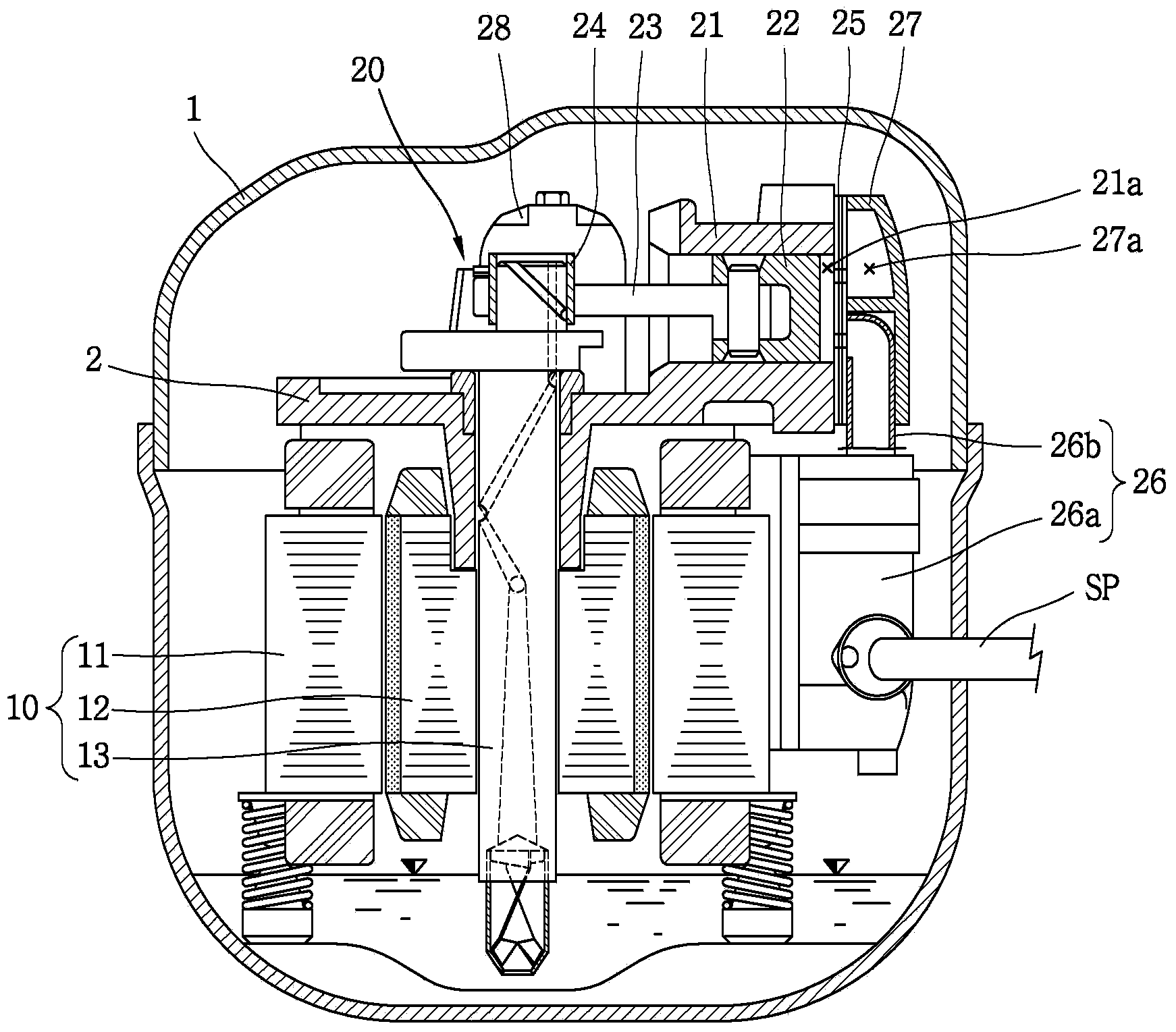
[0016] However, in the conventional reciprocating compressor as described above, the suction muffler 26, the top cover 27, and the discharge muffler 28 are manufactured and assembled as separate components, which not only increases the assembly man-hours, but also causes There is a gap between the muffler 26 and the top cover 27, resulting in leakage of the refrigerant, resulting in reduced performance of the compressor
[0017] In addition, in the conventional reciprocating compressor, since the above-mentioned top cover 27 surrounds and fixes the suction muffler 26, the suction muffler 26 is heated by the refrigerant discharged to the top cover 27, thereby increasing the specific volume of the suction refrigerant and causing a suction loss. , and the cylinder block 21 is overheated by the high-temperature refrigerant discharged to the above-mentioned discharge muffler 28, thereby reducing the compression efficiency of the compression space 21a.
[0018] In addition, in the conventional reciprocating compressor, the connecting pipe 26b of the above-mentioned suction muffler 26 is inserted into the top cover 27 to communicate with the compression space 21a, and the discharge muffler 27 passes through the discharge flow path (not shown) of the cylinder block 21 and Since the compression space 27a is connected, the length of the suction flow path and the discharge flow path becomes longer, and the flow resistance of the refrigerant increases correspondingly, resulting in a decrease in compressor performance.
[0019] In addition, in the conventional reciprocating compressor, the above-mentioned top cover 27 and the discharge muffler 28 are manufactured by casting or sheet metal processing using metal, so there is also a problem that the manufacturing cost increases due to increased material costs and low workability.
[0020] In addition, in the conventional reciprocating compressor, the internal spaces of the suction muffler 26 and the discharge muffler 28 each have a plurality of silencing spaces, but in the case of a small compressor, the suction muffler 26 and the discharge muffler 28 The size is reduced and the formation of complex sound-absorbing space in its internal space is restricted
Conversely, when simply forming the sound-absorbing spaces of the silencers 26 and 28 in consideration of this problem, there is a problem that the sound-absorbing effect is reduced accordingly.

Method used


Image

  • Muffler for compressor and compressor having the same
  • Muffler for compressor and compressor having the same
  • Muffler for compressor and compressor having the same

Examples


Embodiment Construction

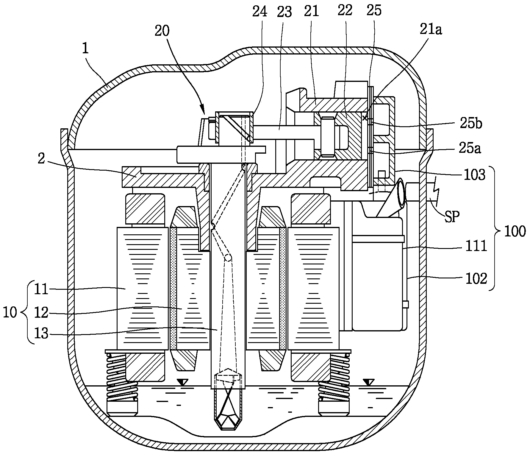
[0045] Next, the silencer for a compressor and the compressor having the silencer for a compressor according to the present invention will be described in detail using an embodiment shown in the drawings.

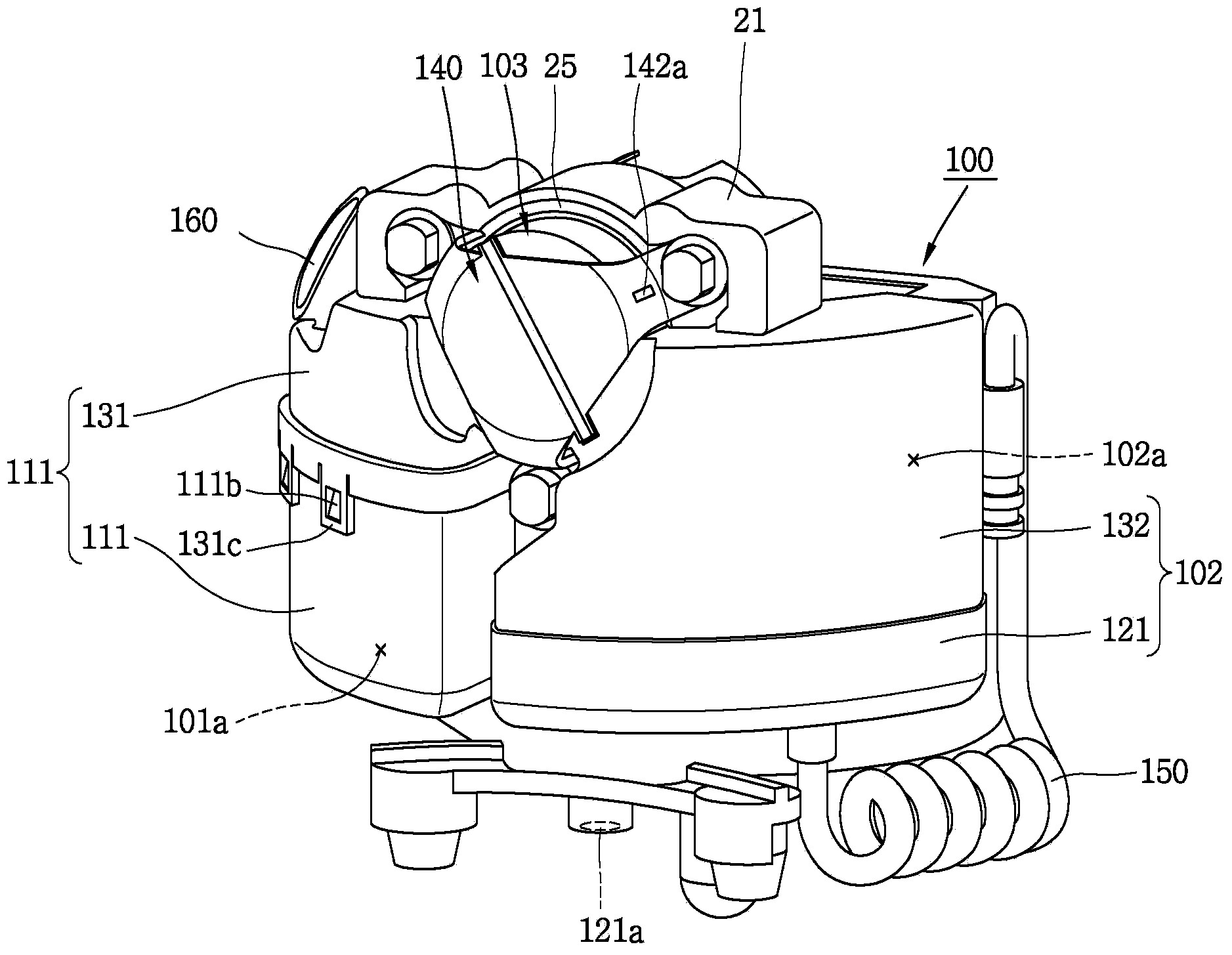
[0046] figure 2 is a longitudinal sectional view showing a reciprocating compressor having an integrated muffler of the present invention, image 3 is viewed from the front figure 2 A perspective view of the one-piece muffler, Figure 4 is to be used for fixing on the compression part figure 2 The fixed member of the one-piece muffler is shown in perspective view separated, Figure 5 is viewed from the back figure 2 A perspective view of the one-piece muffler.

[0047] Such as figure 2 As shown, the reciprocating compressor with the muffler for the compressor of the present invention may include: a casing 1; an electric part 10, which is arranged in the inner space of the above-mentioned casing 1, and is composed of a stator 11, a rotor 12 and a rotating shaft 13...


PUM


Abstract

In a muffler for a compressor and a compressor having the same according to the present disclosure, an integral formation of a suction noise unit and a discharge noise unit may reduce the number of components for configuring a suction side muffler and a discharge side muffler so as to reduce a leakage of a refrigerant generated at an assembled portion of the muffler and also reduce a suction passage and a discharge passage in length. Also, the division between the suction noise unit and the discharge noise unit may prevent a discharged refrigerant from heating a sucked refrigerant, which may result in a reduction of a suction loss. The formation of the suction noise unit and the discharge noise unit using a plastic material may result in a reduction of fabricating costs. In addition, the structures of the suction side noise space and the discharge side noise space may be simplified and noise removal effect can be increased using the suction chamber and the discharge chamber. This may result in a reduction of an entire size of the muffler and improvement of the noise effect.

Description

technical field [0001] The present invention relates to a hermetic compressor, and more particularly, to a compressor muffler in which a suction muffler and a discharge muffler are integrally formed, and a compressor provided with the compressor muffler. Background technique [0002] Generally speaking, a hermetic compressor has an electric part that generates driving force inside the closed casing and a compression part that receives the power transmission of the electric part to compress the refrigerant, and is mainly used in refrigeration systems such as refrigerators and air conditioners. [0003] Hermetic compressors can be classified into various types such as rotary compressors, scroll compressors, and reciprocating compressors according to the compression method and the type of refrigerant used. A reciprocating compressor is a method in which a piston reciprocates in a cylinder to compress a refrigerant. [0004] Reciprocating compressors can be divided into vibrati...

Claims


Application Information

Patent Timeline
Patent Type & Authority Applications(China)
IPC IPC(8): F04B39/00
CPCF04B39/0061F04B39/00F04B39/0083F04B39/0072F04B39/125F04B39/14F04B53/00F04B39/0027
Inventor 赵宰皓
Owner LG ELECTRONICS INC
Learn More